© 2013
400_D - 09/13
5 of 32
Zone
1
2
3
4
Thermostat Load
Zone Valve Load
Floating
Action (VA)
Control
Load (VA)
Total Zone Load
+
+
+
+
+
2
Transformer
must exceed:
VA
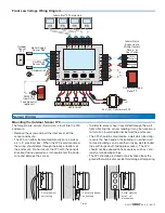
Control Wiring
Line Voltage Wiring
-----------------------------------------------------------------------------------
-----------------------------------------------------------------------------------
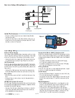
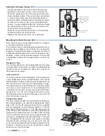
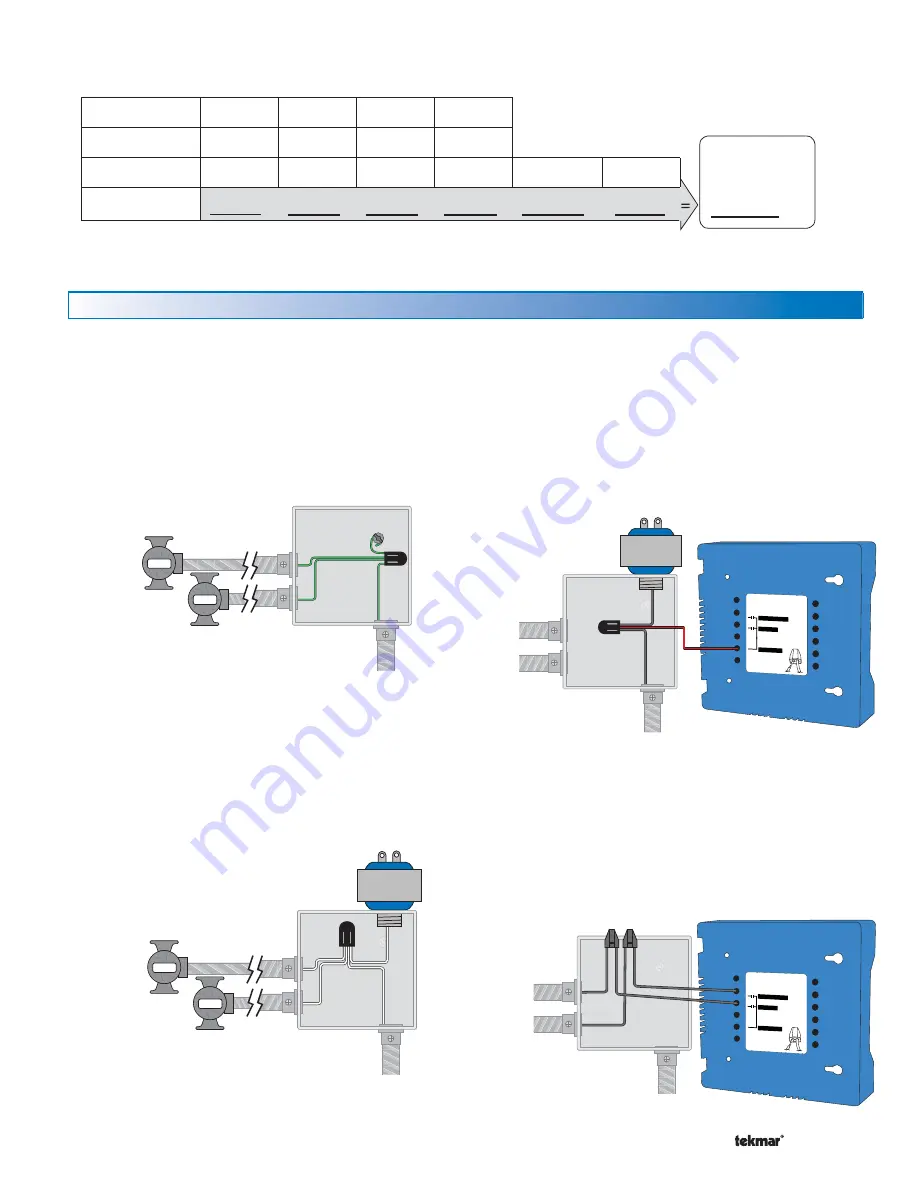
Ground the Pumps
Connect the pump grounds to the power supply
ground as shown in Figure 1. The ground wire must
also be grounded to the electrical box.
•
CAUTION: TURN ALL POWER OFF BEFORE PERFORMING ANY WIRING.
Pump
Leads
DHW Pump
Boil System Pump
Power Source
(L,N)
Pump
Pump
Figure 1 - Connect
Ground Wires
DHW Pump
Boil System Pump
Power Source
(L,N)
Pump
Pump
Figure 2 - Connect
Neutral Wires
Strip wires 1/2 inch
(13 mm). Installed
wires are not removable.
12-18 AWG
DHW Pump
Pump Power L
400
Boil System Pump
DHW Pump
Boil System Pump
Power
Source
(L,N)
Figure 3 - Connect
Line Voltage (Hot)
Strip wires 1/2 inch
(13 mm). Installed
wires are not removable.
12-18 AWG
DHW Pump
Pump Power L
400
Boil System Pump
DHW Pump
Power
Source
(L,N)
Boil System Pump
Figure 4 - Connect
Pump Line (Hot)
Wire the Pump Neutrals
Connect the Neutral (N) wires from each pump and wire
to the 115 V (ac) Neutral (N) wire. If the transformer has
been mounted to this electrical box, connect its neutral
wire with this group. This is shown in Figure 2.
•
Wire the Pump Power (L)
Connect the 115 V (ac) line voltage (L) wire to the red
Pump Power (L) wire on the back of the House Control
and to the 115 V (ac) side of the transformer. Use a
wire nut or approved connector. See Figure 3.
•
Wire the Pumps
Wire each remaining line voltage pump wire into the
push-in wire connector of the corresponding pump
lead on the back of the House Control. This is shown
in Figure 4.
•
The following chart is provided to simplify transformer sizing:

