C
L E A R
P
A T H
M C / S D
U
S E R
M
A N U A L
R
E V
.
3 . 0 9
1 1 9
T
EKNIC
,
I
NC
. T
EL
.
(585)
784-7454
M
OVE TO
S
ENSOR
P
OSITION
M
ODE
D
ESCRIPTION
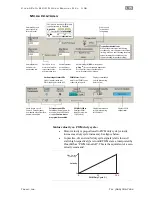
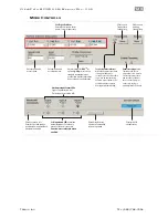
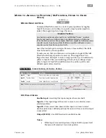
This mode is mainly intended to be used in two-position back and forth
applications (like replacing a pneumatic cylinder). Use ClearPath digital
inputs to spin the shaft CW or CCW. Wire position sensors or switches in
series with ClearPath inputs to make an inexpensive two position
actuator.
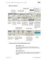
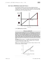
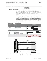
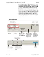
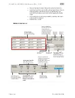
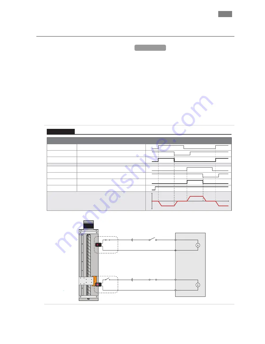
Place sensors at opposite ends of your motion path and wire them into the
appropriate ClearPath inputs. See illustration below.
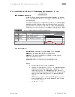
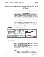
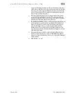
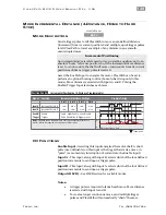
Assert the Enable Input to energize the motor. Apply User Commands to
start motion. ClearPath moves CW or CCW until it interrupts a sensor. It
then holds position until you issue a new User Command in the opposing
direction. See table below for Input states and timing details.
Signal
Function
Example Timing
Move to Sensor Position
Position Control
Wired in series with Input A
Wired in series with Input A
Wired in series with Input B
Wired in series with Input B
Input A
CW Move Request
CCW Move Request
Enable:
High=Enable Low=Disable
Sensor A
User Command A
Input B
Enable
Sensor B
User Command B
v
Motor velocity vs. time
cw
ccw
0
1
0
1
0
1
0
1
0
1
0
1
0
1
ClearPath Internal
Input A +
Input A -
Input B +
Input B -
5-24VDC
5-24VDC
Normally Closed
Optical Slot Sensors
Sensor
‘A’
Sensor
‘B’
User
Command A
(switch)
User
Command B
(switch)
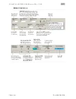
Move to Sensor: Inputs and Timing Diagram with example application sketch
MCVC + MCPV
Available on

