C.
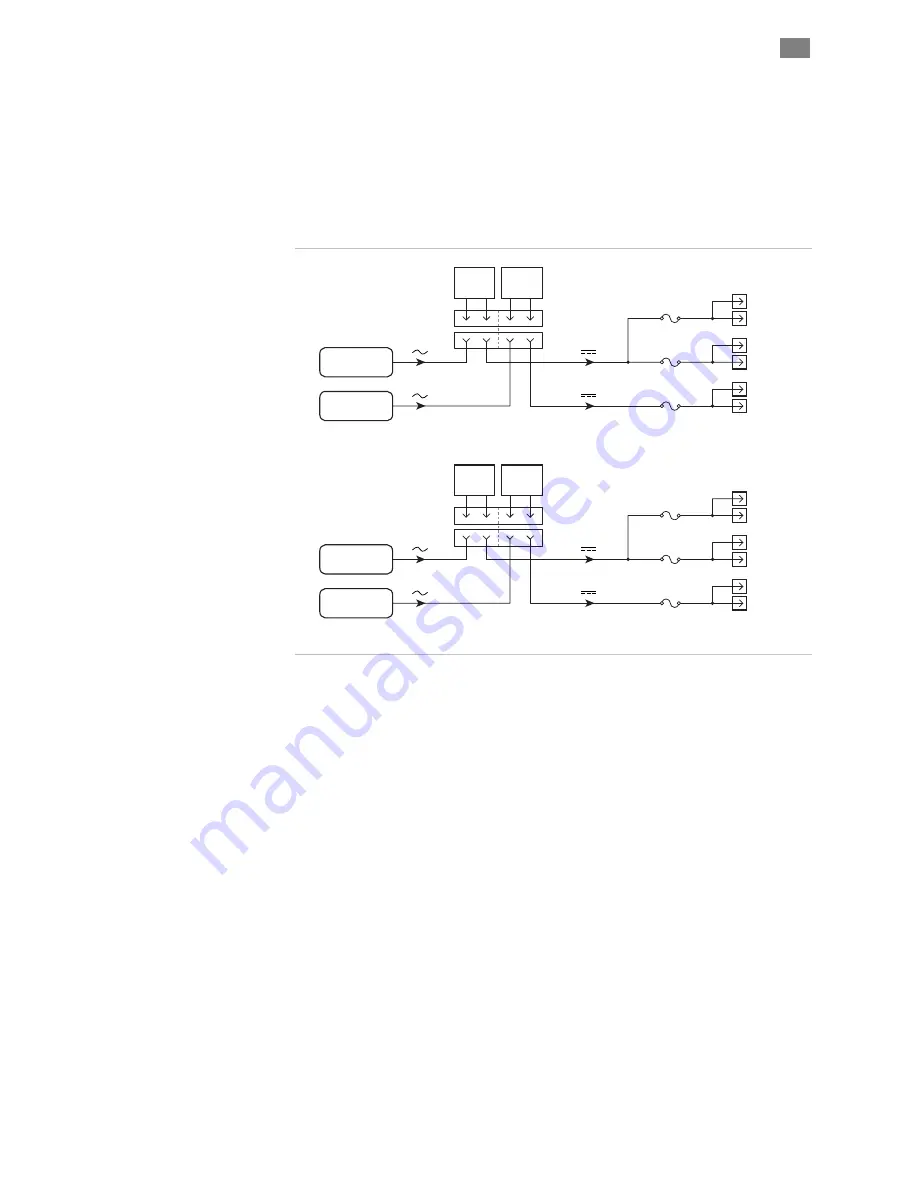
Two power supplies where one supply is on continuously when AC
Control Power is present (circuits 2 and 3), and the other supply is
on only when Hazardous Power is present in the Main Area (circuit
1). See schematic below.
D.
Two power supplies where one supply is on continuously when AC
Control Power is present (circuit 1), and the other supply is on only
when Hazardous Power is present in the Main Area (circuit 2 and
3). See schematic below.
P11-B
P11-A
P10-B
P10-A
P9-B
P9-A
J5
F10
F9
F8
CKT. 3
CKT. 2
CKT. 1
10A max.
10A max.
10A max.
24VDC
24VDC
P11-B
P11-A
P10-B
P10-A
P9-B
P9-A
J5
F10
F9
F8
CKT. 3
CKT. 2
CKT. 1
10A max.
10A max.
10A max.
24VDC
24VDC
front panel
fuses
rear panel
connectors
Main AC
Hazard Power
AC Control
Power
Main AC
Hazard Power
AC Control
Power
Configuration C
Configuration D
Dual 24VDC supply configurations C and D
Design Note:
Use 14 AWG wire with a temperature rating of 90°C or
greater or 12AWGwhen fabricating AC wiring to any connected 24V
power supply. 12 AWG or larger wire if it has insulation rated at or above
70 degrees C). Note: Your 24VDC supplies should have an internal fuse
or other current limiting device to protect against catastrophic failure of
the supply itself (this is typical of most commercially available drives).
Refer to Appendix C for a typical cable diagram for connecting the
24VDC supply to the eF-785.
C
ONNECTING
24VDC
LOADS
(P9-P11)
There are 3 circuits for the distribution of 24VDC power which are rated
up to 10A each, for a total of 30A. Each 24V-distribution circuit includes
two distribution connectors on the rear panel: P9A-P9B, P10A-P10B and
P11A-P11B. Each of these three 24V circuits has its own dedicated front
panel fuse (F8, F9, and F10, respectively.) Each fuse has a dedicated a
blown fuse indicator LED.
e F - 7 8 5
I
N S T A L L A T I O N
M
A N U A L
27
T
EKNIC
,
I
NC
F
AX
(585)784-7460
V
OICE
(585)784-7454
Summary of Contents for EF-785
Page 2: ...THIS PAGE INTENTIONALLY LEFT BLANK ...
Page 66: ...APPENDIX C CABLE DIAGRAMS 48 90VDC LOAD AREA TO SST J8A J8B 64 VERSION 1 42 AUGUST 26 2005 ...
Page 68: ...48 90VDC LOAD AREA TO ISC J8A J8B 66 VERSION 1 42 AUGUST 26 2005 ...
Page 70: ...AC SERVO POWER CABLE LOAD AREA J4 68 VERSION 1 42 AUGUST 26 2005 ...
Page 72: ...SST 6000 3000 DC POWER JUMPER CABLE 70 VERSION 1 42 AUGUST 26 2005 ...
Page 74: ...SINGLE 24VDC SUPPLY CABLE J5 72 VERSION 1 42 AUGUST 26 2005 ...
Page 76: ...70 90VDC SUPPLY CABLE SST EMF75 P6 74 VERSION 1 42 AUGUST 26 2005 ...
Page 78: ...40VDC POWER TAP DISTRIBUTION CABLE P18 76 VERSION 1 42 AUGUST 26 2005 ...
Page 80: ...INTEGRATION TESTING CHEATER PLUG SAFETY CONTROL CKTS P12 78 VERSION 1 42 AUGUST 26 2005 ...
Page 82: ...INPUT POWER CABLE J2 80 VERSION 1 42 AUGUST 26 2005 ...


