50
V
E R S I O N
1 . 4 2
/
A
U G U S T
2 6 ,
2 0 0 5
A
UXILIARY
S
AFETY
C
ONNECTOR
(
P
13)
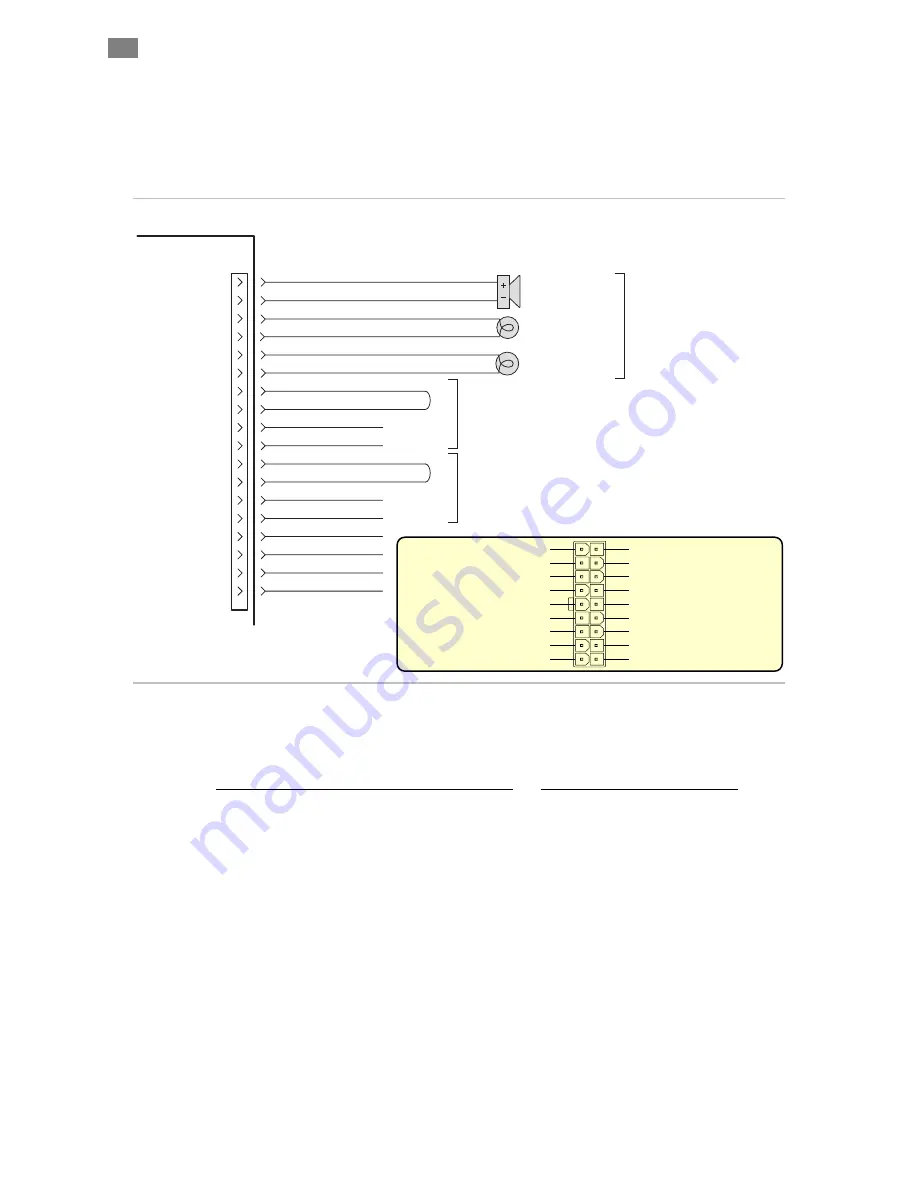
The P13 connector on the eF-785 provides the ability to connect and
control additional contactors in the Main and Option (or Load/Unload)
Areas. The connector also allows external status indicators and alarms to
be connected.
JMP 1
JMP 2
1. 24V Return
2. 24V Return
3. 24V Return
4. Load Hazard Control -
5. 24V Return
6. Main Hazard Control -
7. 24V Return
8. Load Hazard Monitor SW-B
9. Load Hazard Monitor SW-A
10. Safety Alarm
11. Power Applied Output
12. Machine-On Output
13. Load Hazard C
14. Load Area Hazardous
15. Main Hazard C
16. Main Area Hazardous
17. Main Hazard Monitor SW-B
18. Main Hazard Monitor SW-A
Safety Alarm
P13
EF-785
Optional devices
10
1
12
3
11
2
18
17
15
6
9
8
13
4
16
7
14
5
24V Return
Machine-On Output
24V Return
Power Applied Output
24V Return
Main Hazard Monitor SW-A
Main Hazard Monitor SW-B
24V Return
Load Area Hazardous
24V Return
Main Area Hazardous
Load Hazard Control -
Load Hazard C
Main Hazard C
Main Hazard Control -
Load Hazard Monitor SW-A
Load Hazard Monitor SW-B
24VDC
External Buzzer
Machine ON Light
(24VDC)
AC Applied Light
(24VDC)
To optional external
Main Area contactor
To optional external
Load Area contactor
Auxiliary Safety Connector P13 with sample
schematic
(Usually only jumpers Jmp1 & Jmp2 are required)
Auxiliary Safety Connector Part Descriptions
Manufacturer & Part Number
Connector Housing, 18 pin, Minifit
Molex, 39-01-2180
Female crimp socket contacts, 22-28 AWG wire
Molex, 39-00-0047
IMPORTANT NOTE:
When external contactors are not used, the
Main Safe and Load Safe monitoring signals must be jumped to allow the
eF-785 to operate. The two jumpers required are:
Jmp1 Jumper wire P13 pin 8 to 9 for Load safe.
Jmp2 Jumper wire p13 pin 17 to 18 for Main safe.
(An example jumper is shown in Appendix C of this manual.)
S
AFETY
S
YSTEM
P
OWER
C
ONSIDERATIONS
(P12,
P13,
P14)
All safety control circuits are powered by a dedicated, high reliability
24VDC supply internal to the eF-785. This supply is used to power the
safety control relay logic circuits, internal (and external) control
Summary of Contents for EF-785
Page 2: ...THIS PAGE INTENTIONALLY LEFT BLANK ...
Page 66: ...APPENDIX C CABLE DIAGRAMS 48 90VDC LOAD AREA TO SST J8A J8B 64 VERSION 1 42 AUGUST 26 2005 ...
Page 68: ...48 90VDC LOAD AREA TO ISC J8A J8B 66 VERSION 1 42 AUGUST 26 2005 ...
Page 70: ...AC SERVO POWER CABLE LOAD AREA J4 68 VERSION 1 42 AUGUST 26 2005 ...
Page 72: ...SST 6000 3000 DC POWER JUMPER CABLE 70 VERSION 1 42 AUGUST 26 2005 ...
Page 74: ...SINGLE 24VDC SUPPLY CABLE J5 72 VERSION 1 42 AUGUST 26 2005 ...
Page 76: ...70 90VDC SUPPLY CABLE SST EMF75 P6 74 VERSION 1 42 AUGUST 26 2005 ...
Page 78: ...40VDC POWER TAP DISTRIBUTION CABLE P18 76 VERSION 1 42 AUGUST 26 2005 ...
Page 80: ...INTEGRATION TESTING CHEATER PLUG SAFETY CONTROL CKTS P12 78 VERSION 1 42 AUGUST 26 2005 ...
Page 82: ...INPUT POWER CABLE J2 80 VERSION 1 42 AUGUST 26 2005 ...


