background image


å

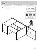
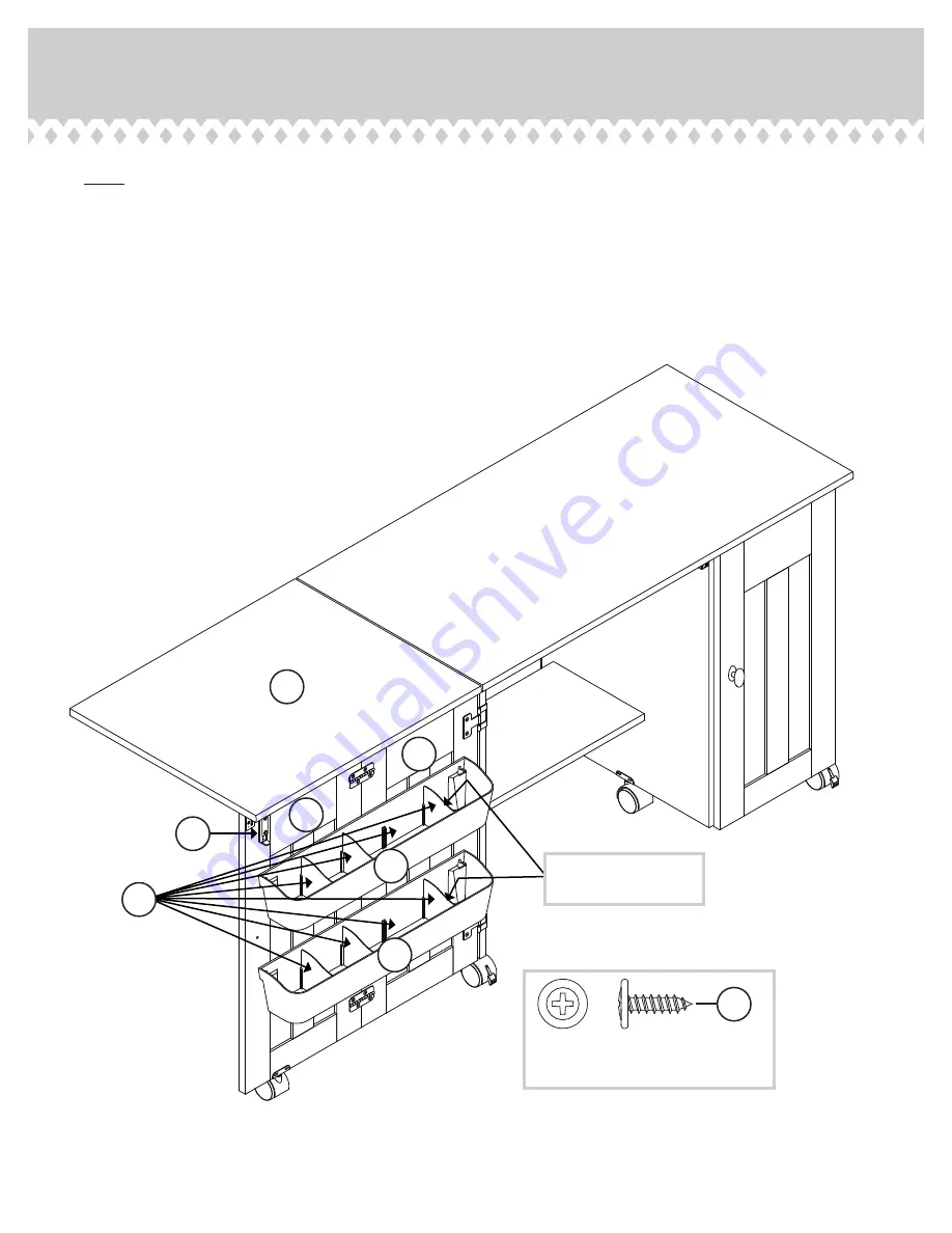
NOTE: The FLIP-UP TOP (E) can be supported by the
DOORS (J and MM). There are two holes in the bottom 
surface of the FLIP-UP TOP (E) for the bolt in the SLIDE 
CATCH (6J) to lock into.


å

Fasten the TRAYS (2D) to the DOORS (J and MM). Use
four BLACK 9/16" LARGE HEAD SCREWS (1S).


å

Now, slide eight TRAY DIVIDERS (3D) into the TRAYS (2D)
as shown.

Step 13

Page 17

E

J

2D

2D

MM

3D

BLACK 9/16" LARGE HEAD SCREW

(4 used for the TRAYS)

1S

The curved edge of the 
DIVIDER should be up.

6J

Summary of Contents for 5414873

Page 1: ...Tidy up Cruise around NOTE THIS INSTRUCTION BOOKLET CONTAINS IMPORTANT SAFETY INFORMATION PLEASE READ AND KEEP FOR FUTURE REFERENCE Sewing Craft Cart Model 5414873 Teknik www teknikoffice co uk ...

Page 2: ... Required Part Identification Hardware Identification Assembly Steps Français Español Safety Warranty Hammer Not actual size No 2 Phillips Screwdriver Tip Shown Actual Size Skip the power trip This time 3 4 5 18 19 21 22 25 26 27 Page 2 ...

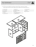
Page 3: ...guish similar parts from each other Use this part identification to help identify similar parts Now you know our ABCs A RIGHT END 1 B LEFT END 1 C2 UPRIGHT 1 D TOP 1 E FLIP UP TOP 1 F BOTTOM 1 G2 MODESTY PANEL 1 H2 SHELF 1 I ADJUSTABLE SHELF 2 J CENTER DOOR 1 K RIGHT DOOR 1 L BACK 1 MM LEFT DOOR 1 A B C2 D E F H2 G2 I I J K L MM Page 3 ...

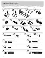
Page 4: ... BLACK 9 16 LARGE HEAD SCREW 40 1S 18S BROWN 1 FLAT HEAD SCREW 2 NON ADJUSTABLE HINGE 2 2H CAM COVER 4 19P ADJUSTABLE HINGE 2 3H METAL PIN 8 1R BLACK 1 2 FLAT HEAD SCREW 2 11S NAIL 13 1N HIDDEN CAM 14 1F CAM DOWEL 14 2F RUBBER SLEEVE 8 2R CASTER 4 2CN LOCKING CASTER 2 2CL TRAY DIVIDER 8 3D TRAY 2 2D KNOB and BACKPLATE 3 72K Page 4 17E CASTER BRACKET 6 STRIKE PLATE 2 6I BLACK 1 15 16 FLAT HEAD SCRE...

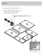
Page 5: ...Push fourteen HIDDEN CAMS 1F into the ENDS A and B UPRIGHT C2 BOTTOM F MODESTY PANEL G2 and SHELF H2 Then insert the metal end of a CAM DOWEL 2F into each HIDDEN CAM 14 used Arrow 1F 2F Insert the metal end of the CAM DOWEL into the HIDDEN CAM Arrow Do not tighten the HIDDEN CAMS in this step C2 A B F H2 G2 Page 5 ...

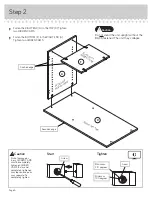
Page 6: ...ace with HIDDEN CAMS Surface with HIDDEN CAMS A D F Start Tighten Arrow Minimum 190 degrees Caution Risk of damage or injury HIDDEN CAMS must be completely tightened HIDDEN CAMS that are not completely tightened may loosen and parts may separate To completely tighten Arrow Maximum 210 degrees Page 6 Do not stand the unit upright without the BACK fastened The unit may collapse Caution ...

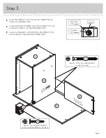
Page 7: ... HEAD SCREWS 113S å Fasten two MAGNETIC CATCHES 5I to the UPRIGHT C2 Use two BLACK 1 1 8 PAN HEAD SCREWS 9S Step 3 Surface with HIDDEN CAMS Surface without HIDDEN CAMS Arrow Minimum 190 degrees Maximum 210 degrees C2 D F G2 5I Page 7 BLACK 1 1 8 PAN HEAD SCREW 2 used for the MAGNETIC CATCHES 9S BLACK 1 15 16 FLAT HEAD SCREW 2 used in this step 113S ...

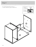
Page 8: ...å Fasten the LEFT END B to the TOP D and MODESTY PANEL G2 Tighten four HIDDEN CAMS Step 4 B D G2 Surface with HIDDEN CAMS Arrow Minimum 190 degrees Maximum 210 degrees Page 8 ...

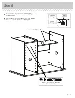
Page 9: ...to the LEFT END B Tighten two HIDDEN CAMS å Fasten the SHELF H2 to the UPRIGHT C2 Use two BLACK 1 15 16 FLAT HEAD SCREWS 113S Step 5 Arrow Minimum 190 degrees Maximum 210 degrees B C2 H2 Page 9 BLACK 1 15 16 FLAT HEAD SCREW 2 used in this step 113S ...

Page 10: ...Push on opposite corners of your unit if needed to make it square å Fasten the BACK L to your unit using the NAILS 1N D L Finished surface The BACK L should be against the bottom surface of the TOP D These holes must be here Page 10 Do not stand the unit upright without the BACK fastened The unit may collapse Caution NAIL 13 used in this step 1N ...

Page 11: ...ten two HINGES 16H to the TOP D and FLIP UP TOP E Use eight BLACK 9 16 LARGE HEAD SCREWS 1S BLACK 9 16 LARGE HEAD SCREW 8 used in this step 1S 16H D E Surface with holes Page 11 Remember Righty tighty Lefty loosey ...

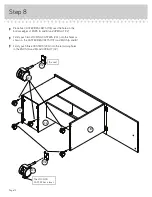
Page 12: ...d UPRIGHT C2 å Firmly push two LOCKING CASTERS 2CL into the holes as shown in the CASTER BRACKETS 17E and ENDS A and B å Firmly push three CASTERS 2CN into the remaining holes in the ENDS A and B and UPRIGHT C2 Step 8 17E 17E 2CL 2CN The LOCKING CASTER has a lever A B C2 Page 12 5 used ...

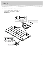
Page 13: ...en two NON ADJUSTABLE HINGES 2H to the RIGHT DOOR K Use four BLACK 9 16 LARGE HEAD SCREWS 1S Step 9 Page 13 BLACK 9 16 LARGE HEAD SCREW 4 used for the HINGES 1S The NON ADJUSTABLE HINGE will NOT have a gap here 2H K 6I BLACK 1 2 FLAT HEAD SCREW 1 used for the STRIKE PLATE 11S Indented holes ...

Page 14: ... BLACK 9 16 LARGE HEAD SCREWS 1S å Fasten a KNOB and BACKPLATE 72K to the RIGHT DOOR K Use a GOLD 1 MACHINE SCREW 50S Step 10 BLACK 9 16 LARGE HEAD SCREW 4 used for the HINGES 1S GOLD 1 MACHINE SCREW 1 used for the KNOB 50S A K 72K Page 14 Pro Tip Lift with your legs And you know your arms ...

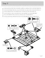
Page 15: ...6J to the CENTER DOOR J Use two BROWN 1 FLAT HEAD SCREWS 18S å Place a CASTER BRACKET 17E over the hole in the bottom edge of the CENTER DOOR J å Firmly push the remaining CASTER 2CN into the hole in the CASTER BRACKET 17E and CENTER DOOR J Step 11 BLACK 9 16 LARGE HEAD SCREW 16 used for the HINGES 1S BROWN 1 FLAT HEAD SCREW 2 used for the SLIDE CATCH 18S 16H 6J 17E 2CN 3H Page 15 J MM The ADJUSTA...

Page 16: ...our BLACK 9 16 LARGE HEAD SCREWS 1S å Fasten a KNOB and BACKPLATE 72K to each DOOR J and MM Use two GOLD 1 MACHINE SCREWS 50S Step 12 B J MM 72K BLACK 9 16 LARGE HEAD SCREW 4 used for the HINGES 1S GOLD 1 MACHINE SCREW 2 used for the KNOBS 50S Page 16 ...

Page 17: ...E for the bolt in the SLIDE CATCH 6J to lock into å Fasten the TRAYS 2D to the DOORS J and MM Use four BLACK 9 16 LARGE HEAD SCREWS 1S å Now slide eight TRAY DIVIDERS 3D into the TRAYS 2D as shown Step 13 Page 17 E J 2D 2D MM 3D BLACK 9 16 LARGE HEAD SCREW 4 used for the TRAYS 1S The curved edge of the DIVIDER should be up 6J ...

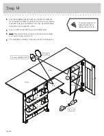
Page 18: ... PINS å Push a CAM COVER 19P onto each HIDDEN CAM å NOTE Please read the back pages of the instruction booklet for important safety information å This completes assembly Clean with a damp cloth Wipe dry Step 14 8 used 2R 1R I 4 used To cover HIDDEN CAMS 19P 20 lbs 25 lbs 25 lbs 25 lbs 25 lbs 75 lbs A Page 18 C I 25 lbs If you re doing this to help a friend don t leave without a bite 25 lbs ...

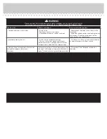
Page 19: ... drawers Place the heavier items on the lower shelves or in lower drawers Improperly moving the cart Risk of injury or equipment damage The cart can tip if not moved carefully over obstacles or across a changing floor surface for example from a wood floor to a carpeted floor Lift the cart so the casters clear any obstacles or abrupt changes in the floor surface Placing TVs on furniture items that are ...

Reviews: