background image

 å

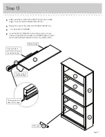
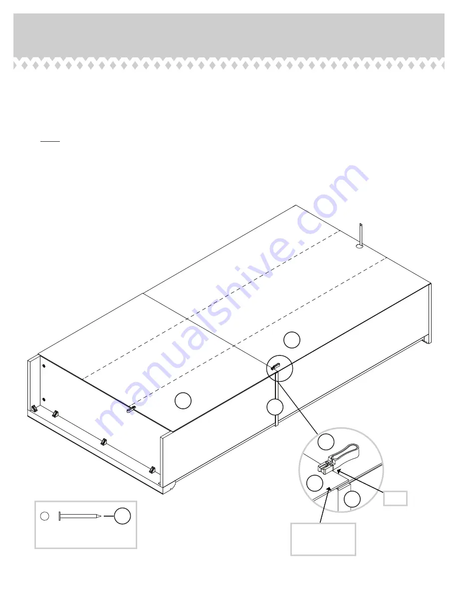
Position the BACK (I) over the lower portion of your unit, making equal margins along the bottom
and side edges. 

 å

Fasten the BACK (I) to the bottom and side edges of your unit using the NAILS (1N) using the Nail
Holder tool as shown in the previous step.

 å

NOTE: The BACK (I) will overlap the LARGE BACK (H2) as shown in the enlarged diagram.

 å

Fasten the BACK and LARGE BACK to the SHELF (G2) using the remaining NAILS (1N). by
following the enlarged diagram below.

 å

Diagram: Place the bead of the Nail Holder down onto the LARGE BACK (H2) and BACK (I). Place
a NAIL into the nail slot of the Nail Holder. Tap the nail through the BACKS (H2 and I). Repeat this to 
tap the remaining NAILS on the top edge of the BACK (I).

Step 11

I

Unfi

 nished 

sur

face

H2

I

G2

The BACK (I)
overlaps the 
LARGE BACK (H2).

Bead

H2

NAIL

(31 used in this step)

1N

Page 15

G2

Summary of Contents for 5420173

Page 1: ...RUCTION BOOKLET CONTAINS IMPORTANT SAFETY INFORMATION PLEASE READ AND KEEP FOR FUTURE REFERENCE 5 Shelf Bookcase Barrister Home Model 5420173 Great for all those books you ll never read Teknik www teknikoffice co uk ...

Page 2: ...arts will have a label or an inked letter on the edge to help distinguish similar parts from each other Use this part identification to help identify similar parts A2 RIGHT END 1 B2 LEFT END 1 C LOWER RIGHT END 1 D LOWER LEFT END 1 E2 TOP 1 F BOTTOM 1 G2 SHELF 1 H2 LARGE BACK 1 I BACK 1 J ADJUSTABLE SHELF 3 K END MOLDING 2 M25 TOP MOLDING 1 M48 BASE 1 N SHELF MOLDING 3 O SKIRT 1 P LOWER END MOLDING...

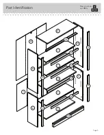
Page 3: ...Part Identification Now you know our ABCs Page 3 A2 B2 C D E2 F G2 H2 I J K N O P N N K P J J M48 M25 ...

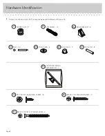
Page 4: ...rdware with your unit Page 4 HIDDEN CAM 12 1F CAM DOWEL 12 2F CAM COVER 8 13P HOLE PLUG 3 14P METAL PIN 12 1R BLACK 1 1 8 PAN HEAD SCREW 3 9S BLACK 9 16 LARGE HEAD SCREW 16 1S NAIL 55 1N ANGLE BRACKET 8 27G BLACK 1 15 16 FLAT HEAD SCREW 4 113S FURNITURE TIPPING RESTRAINT KIT 1 97 ...

Page 5: ...he floor å Push twelve HIDDEN CAMS 1F into the ENDS A2 and B2 LOWER ENDS C and D and BOTTOM F Then insert the metal end of a CAM DOWELS 2F into the HIDDEN CAMS Page 5 Insert the metal end of the CAM DOWEL into the HIDDEN CAM Arrow Do not tighten the HIDDEN CAMS in this step A2 B2 C D F Arrow 1F 2F 12 used ...

Page 6: ...ETY STRAP to the TOP E2 Use the provided BLACK 9 16 LARGE HEAD SCREW å NOTE Position the SAFETY STRAP exactly as shown Page 6 E2 Surface with holes Long finished edge Remember Righty tighty Lefty loosey BLACK 9 16 LARGE HEAD SCREW 1 used for the SAFETY STRAP Safety strap 97 ...

Page 7: ...ghtened may loosen and parts may separate To completely tighten Arrow Maximum 210 degrees A2 B2 E2 Notched edge Notched edge Surface with HIDDEN CAMS Surface without HIDDEN CAMS Surface with holes Do not stand the unit upright without the BACK fastened The unit may collapse Caution å Fasten the TOP E2 to the ENDS A2 and B2 Tighten four HIDDEN CAMS Long finished edge ...

Page 8: ...o the holes in the TOP MOLDING M25 å Slide the END MOLDINGS K onto the notched edges of the ENDS A2 and B2 å U S Patent No 5 499 886 Page 8 Notched edge Notched edge A2 B2 K K Slide the END MOLDINGS K onto the notched edges The large groove is closer to this edge The large groove is closer to this edge Curved edge E2 14P BLACK 1 1 8 PAN HEAD SCREW 3 used in this step 9S M25 ...

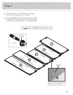
Page 9: ...NDS A2 and B2 Use four BLACK 1 15 16 FLAT HEAD SCREWS 113S Step 5 Page 9 A2 B2 G2 Long finished edge BLACK 1 15 16 FLAT HEAD SCREW 4 used in this step 113S Don t worry It isn t Rome This can be built in a day Surface with more holes ...

Page 10: ...LF G2 Tighten two HIDDEN CAMS å Fasten the BOTTOM F to the LOWER LEFT END D Tighten two HIDDEN CAMS Page 10 Arrow Minimum 190 degrees Maximum 210 degrees Notched edge Surface with HIDDEN CAMS G2 F Surface with HIDDEN CAMS These holes must be here D ...

Page 11: ... notched edges of the LOWER ENDS C and D å U S Patent No 5 499 886 Step 7 Page 11 Arrow Minimum 190 degrees Maximum 210 degrees Notched edge Notched edge C D P P Slide the LOWER END MOLDINGS P onto the notched edges G2 F Surface without HIDDEN CAMS The large groove is closer to this edge The large groove is closer to this edge ...

Page 12: ...ARGE HEAD SCREWS 1S å NOTE Be sure the ANGLE BRACKETS are even with the edges of the LOWER ENDS and BOTTOM å Fasten the BASE M48 to the LOWER ENDS C and D and BOTTOM F Use five BLACK 9 16 LARGE HEAD SCREWS 1S C D F 27G 27G 27G BLACK 9 16 LARGE HEAD SCREW 10 used in this step 1S Finished surface M48 Wide edge ...

Page 13: ...9 16 LARGE HEAD SCREWS 1S å NOTE There are no pre drilled holes in the SKIRT The SCREWS will tighten into the groove å Carefully turn your unit over onto its front edges G2 O 27G BLACK 9 16 LARGE HEAD SCREW 6 used in this step 1S TURN OVER ON LONG EDGE TURN OVER ON LONG EDGE Do not stand the unit upright without the BACK fastened The unit may collapse Caution ...

Page 14: ...S should be 5 1 2 apart 1 1 2 from the corners and be sure the NAILS are 1 2 from each fold line in the BACK Place a NAIL 1N into the nail slot of the Nail Holder Tap the NAIL through the BACK and into lower edge of the END shown Remove the Nail Holder from the NAIL and completely tap the NAIL in with your hammer Repeat this to tap the remaining NAILS in the top and side edges of the BACK å NOTE D...

Page 15: ... in the enlarged diagram å Fasten the BACK and LARGE BACK to the SHELF G2 using the remaining NAILS 1N by following the enlarged diagram below å Diagram Place the bead of the Nail Holder down onto the LARGE BACK H2 and BACK I Place a NAIL into the nail slot of the Nail Holder Tap the nail through the BACKS H2 and I Repeat this to tap the remaining NAILS on the top edge of the BACK I Step 11 I Unfin...

Page 16: ...a hand drill press the screw slightly onto the drywall just below the top surface of your unit so the SAFETY STRAP will not be visible 3 Apply pressure turn the screw until a pilot hole is made and the nylon sheath slips through 4 Turn the screw until it is flush against the wall and you feel a firm resistance 5 Continue to turn until the screw starts spinning freely å NOTE Before moving your unit t...

Page 17: ...atent No 5 499 886 å Insert the METAL PINS 1R into the hole locations of your choice in the ENDS A2 and B2 and LOWER ENDS C and D Set the ADJUSTABLE SHELVES J onto the METAL PINS Step 13 Page 17 J Slide the SHELF MOLDING N onto the notched edge N These surfaces should be even 1R 12 used J J J A2 C D B2 The large groove is closer to this edge Notched edge ...

Page 18: ... each visible HIDDEN CAM å NOTE Please read the back pages of the instruction booklet for important safety information å This completes assembly Clean with a damp cloth Wipe dry Page 18 To cover HIDDEN CAMS 8 used 13P No load 40 lbs 50 lbs 30 lbs 30 lbs 30 lbs ...

Page 19: ...p over or break if improperly moved Physical injury Furniture can be very heavy Unload shelves from top to bottom before moving the furniture Do not push furniture especially on a carpeted floor Have a friend help you lift the item and set it in place This unit must be positioned against a wall Children climbing on the shelves can cause the product to tip Risk of injury or death Do not allow childr...

Reviews: