background image

Table of Contents

Assembly Tools Required

Part Identifi cation

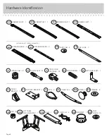
Hardware Identifi cation

Assembly Steps

Français

Español

Safety

Warranty

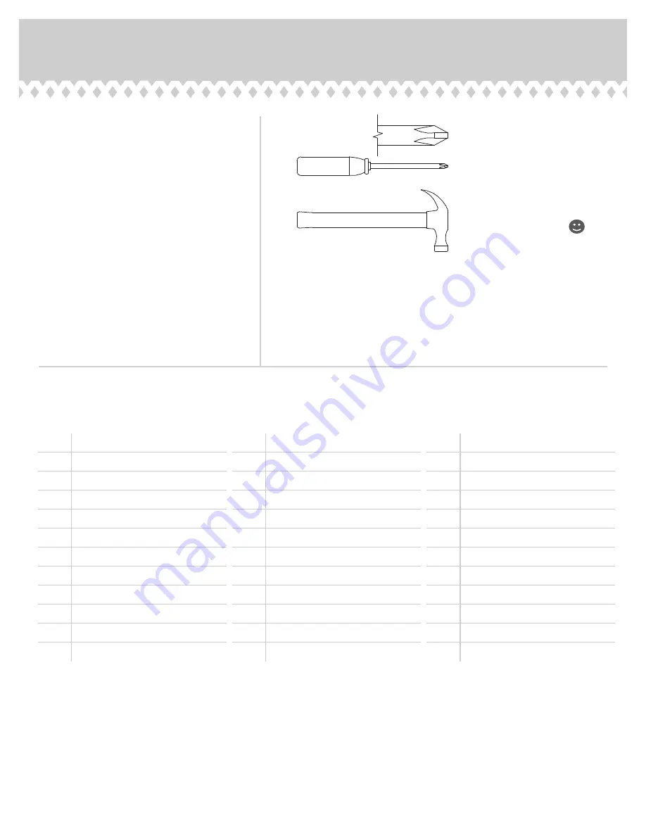
Hammer

Not actual size 

No. 2 Phillips Screwdriver
Tip Shown Actual Size

2-3

4-5

6-38

39-43

44-48

49-50

51

A

RIGHT END (1)

B

LEFT END (1)

C

TOP (1)

D

LIFT TOP (1)

D14

LARGE RIGHT DRAWER SIDE (1)

D15

LARGE LEFT DRAWER SIDE (1)

D20

SMALL RIGHT DRAWER SIDE (1)

D21

SMALL LEFT DRAWER SIDE (1)

D74

SMALL DRAWER BACK (1)

D78

LARGE DRAWER BACK (1)

D716 DRAWER BOTTOM (2)

E

UPRIGHT (1)

F

LARGE BOTTOM (1)

G

BACK STRETCHER (1)

H

STRETCHER (1)

I

LONG BACK (1)

J

SMALL BACK (1)

K

FRONT (1)

L

SHELF (1)

M

PEDESTAL LEFT END (1)

N

PEDESTAL RIGHT END (1)

O

FRONT LEG (1)

P

LEFT FRONT LEG (1)

Q

RIGHT FRONT LEG (1)

R

REAR LEG (1)

S

LEFT REAR LEG (1)

T

RIGHT REAR LEG (1)

U

PEDESTAL BOTTOM (1)

V

PEDESTAL BACK (1)

W

LARGE DRAWER BOX FRONT (1)

X

LIFT TOP STRETCHER (1)

Y

SMALL DRAWER BOX FRONT (1)

Z

END MOLDING (1)

AA

SMALL UPRIGHT (1)

BB

LARGE DRAWER FRONT (1)

CC

SMALL DRAWER FRONT (1)

Page 2

Summary of Contents for 5422378

Page 1: ...You could totally write a novel on this Sit Stand Desk Model 5422378 ...

Page 2: ...SIDE 1 D21 SMALL LEFT DRAWER SIDE 1 D74 SMALL DRAWER BACK 1 D78 LARGE DRAWER BACK 1 D716 DRAWER BOTTOM 2 E UPRIGHT 1 F LARGE BOTTOM 1 G BACK STRETCHER 1 H STRETCHER 1 I LONG BACK 1 J SMALL BACK 1 K FRONT 1 L SHELF 1 M PEDESTAL LEFT END 1 N PEDESTAL RIGHT END 1 O FRONT LEG 1 P LEFT FRONT LEG 1 Q RIGHT FRONT LEG 1 R REAR LEG 1 S LEFT REAR LEG 1 T RIGHT REAR LEG 1 U PEDESTAL BOTTOM 1 V PEDESTAL BACK ...

Page 3: ... have a label or an inked letter on the edge to help distinguish similar parts from each other Use this part identification to help identify similar parts Now you know our ABCs A B C D E F G H I J K L M N O P Q R S T U V W X Y Z AA BB CC D14 D15 D20 D21 D74 D78 D716 D716 Page 3 ...

Page 4: ...2 37G EXTENSION SET SHOWN SEPARATED EXTENSION RAIL 2 35MA EXTENSION SLIDE 2 35MC 141M LIFT TABLE MECHANISM SET 1 NUT 8 24M WASHER 8 13M METAL BRACKET 1 2G ANGLE BRACKET 3 5G 7F TWIST LOCK FASTENER 24 PULL 2 7K 10A SLIDE CAM 4 CAM SCREW 37 8F CORD CLIP 4 9P WOOD DOWEL 7 15F GROMMET 1 10P HIDDEN CAM 37 1F Page 4 CAM COVER 10 12P KNOB 1 188K GLUE 1 177M ...

Page 5: ...GE HEAD SCREW 6 17S GRAY 1 3 8 MACHINE SCREW 4 39S BLACK 7 8 MACHINE SCREW 1 37S 12S BROWN 1 FLAT HEAD SCREW 2 3S GOLD 5 16 FLAT HEAD SCREW 16 BLACK 1 2 FLAT HEAD SCREW 4 11S BLACK 9 16 FLAT HEAD SCREW 2 32S BLACK 3 4 MACHINE SCREW 4 92S BLACK 1 1 4 MACHINE SCREW 4 93S BLACK 1 15 16 FLAT HEAD SCREW 5 113S 30S BLACK 1 9 16 FLAT HEAD SCREW 8 Page 5 ...

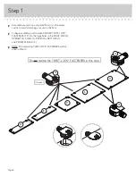
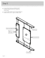
Page 6: ... å To begin assembly push sixteen SAUDER TWIST LOCK FASTENERS 7F into the large holes in the RIGHT END A UPRIGHT E SHELF L PEDESTAL BOTTOM U and PEDESTAL BACK V å NOTE The remaining TWIST LOCK FASTENERS will be used in Step 14 16 used 7F 7F Do not tighten the TWIST LOCK FASTENERS in this step 7F A E L U V Page 6 ...

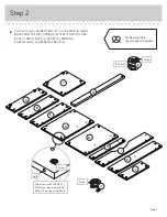
Page 7: ...ard the hole in the edge of the board Hole å Push thirty seven HIDDEN CAMS 1F into the ENDS A and B BACK STRETCHER G UPRIGHT E STRETCHER H LONG BACK I SMALL BACK J FRONT K PEDESTAL ENDS M and N and PEDESTAL BACK V Arrow 1F 1F Arrow Page 7 Some assembly and snacks required 37 used ...

Page 8: ...Step 3 8F å Turn thirty seven CAM SCREWS 8F into the LEGS O P Q R S and T LEFT END B and STRETCHER H O P Q R S T B H 8F 8F Page 8 37 used ...

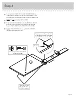
Page 9: ... MOLDING Z onto the PEDESTAL RIGHT END N Line up the groove in the MOLDING over the heads of the SCREWS in the PEDESTAL RIGHT END å NOTE If the MOLDING comes up off of the SCREWS remove it and slide it on again These edges should be even after the MOLDING is slid on BLACK 9 16 FLAT HEAD SCREW 2 used in this step 32S Shoulder Apply pressure with your hands as you guide the MOLDINGS over the SCREWS ...

Page 10: ...D N to the RIGHT REAR LEG T Tighten four HIDDEN CAMS å Fasten the RIGHT FRONT LEG Q to the RIGHT END A and PEDESTAL RIGHT END N Tighten four HIDDEN CAMS Surface with HIDDEN CAMS Surface with HIDDEN CAMS Edge with TWIST LOCK FASTENERS Angled edge END MOLDING Z Angled edge ...

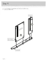
Page 11: ...GHT END A and the CABINET LEFT 40CB to the UPRIGHT E Use four GOLD 5 16 FLAT HEAD SCREWS 3S through holes 1 and 3 GOLD 5 16 FLAT HEAD SCREW 4 used in this step 3S 1 2 3 4 Roller end Roller end A E Don t worry It isn t Rome This can be built in a day 1 2 3 4 ...

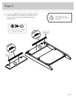
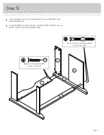
Page 12: ...FLAT HEAD SCREWS 3S through holes 1 and 3 å NOTE For each EXTENSION RAIL turn a SCREW into the hole shown in the enlarged diagram Then slide the inner cartridge of the EXTENSION RAIL in to find the other hole that lines up with the hole in the ENDS Turn a SCREW into this hole å NOTE The EXTENSION SLIDES 35MC will be used later for the DRAWERS GOLD 5 16 FLAT HEAD SCREW 4 used in this step 3S Push th...

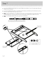
Page 13: ...rt the WOOD DOWELS 15F into the holes Wipe away the excess GLUE å Now fill the holes in the LEFT END B and STRETCHER H 1 4 to 1 2 full with GLUE Then insert the WOOD DOWELS 15F in the LEFT REAR LEG S into these holes Tighten three HIDDEN CAMS Wipe away the excess GLUE B H S Surface with HIDDEN CAMS Surface with HIDDEN CAMS 1 2 Angled edge The CAM SCREWS should be here Fill the holes 1 4 to 1 2 full...

Page 14: ...Step 9 Page 14 å Fasten the LONG BACK I to the LEFT END B Tighten two HIDDEN CAMS B Surface with HIDDEN CAMS I Curved edge ...

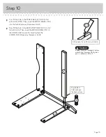
Page 15: ...e hole in the BACK STRETCHER G 1 4 to 1 2 full with GLUE Then insert the WOOD DOWEL 15F in the STRETCHER H into this hole Tighten the HIDDEN CAM Wipe away the excess GLUE Inspect the parts thoroughly before assembling Disassembly of glued parts is extremely difficult Caution 15F G H The HIDDEN CAM will be on the back surface Fill the holes 1 4 to 1 2 full with GLUE 177M ...

Page 16: ...Step 11 Page 16 E M R å Fasten the UPRIGHT E and PEDESTAL LEFT END M to the REAR LEG R Tighten four HIDDEN CAMS Angled edge Surface with HIDDEN CAMS These two small holes must be here Roller end ...

Page 17: ...he LONG BACK I Use two BROWN 1 FLAT HEAD SCREWS 12S å Fasten the PEDESTAL LEFT END M to the BACK STRETCHER G Use two BLACK 1 15 16 FLAT HEAD SCREWS 113S BROWN 1 FLAT HEAD SCREW 2 used in this step 12S BLACK 1 15 16 FLAT HEAD SCREW 2 used in this step 113S ...

Page 18: ... Tighten six TWIST LOCK FASTENERS 7F å Push the two remaining TWIST LOCK FASTENERS 7F into the long edge of the LARGE BOTTOM F E B I F 7F 7F 7F 7F How to use the SAUDER TWIST LOCK FASTENER 1 Insert the dowel end of the FASTENER into the hole of the adjoining part NOTE The dowel end of the FASTENER must remain fully inserted in the hole of the adjoining part while locking the FASTENER 2 Tighten the...

Page 19: ...hen insert two WOOD DOWELS 15F into the holes Wipe away the excess GLUE å Now fill the holes in the FRONT LEGS O and P a 1 4 to 1 2 full with GLUE Then insert the WOOD DOWELS 15F in the FRONT K into the holes in the FRONT LEGS O and P Tighten four HIDDEN CAMS Wipe away the excess GLUE 1 2 Angled edge Angled edge S u r f a c e w i t h H I D D E N C A M S These holes must be here Fill the holes 1 4 t...

Page 20: ...ipe away the excess GLUE å Now fill the holes in the LEFT FRONT LEG P 1 4 to 1 2 full with GLUE Then insert the WOOD DOWELS 15F in the LEFT END B and STRETCHER H into the holes in the LEFT FRONT LEG P Tighten seven HIDDEN CAMS Wipe away the excess GLUE å Fasten the KNOB 188K to the FRONT K Use a BLACK 7 8 MACHINE SCREW 37S H M BLACK 7 8 MACHINE SCREW 1 used for KNOB 37S 188K ...

Page 21: ...es in the LARGE BOTTOM F å Fasten the SMALL UPRIGHT AA to the LARGE BOTTOM F Use three BLACK 1 15 16 FLAT HEAD SCREWS 113S å Fasten the SMALL BACK J to the REAR LEG R Finished edge S u r f a c e w i t h H I D D E N C A M S 9P Finished edge BLACK 1 15 16 FLAT HEAD SCREW 3 used in this step 113S R ...

Page 22: ...TTOM U and SHELF L to the PEDESTAL BACK V Tighten four TWIST LOCK FASTENERS Step 17 L U V Page 22 Surface with TWIST LOCK FASTENERS Surface without TWIST LOCK FASTENERS S u r f a c e w i t h T W I S T L O C K F A S T E N E R S ...

Page 23: ...å Fasten the SHELF L and PEDESTAL BOTTOM U to the PEDESTAL LEFT END M Tighten four TWIST LOCK FASTENERS å Fasten the PEDESTAL BACK V to the REAR LEG R Tighten two HIDDEN CAMS Step 18 L U V R Page 23 M ...

Page 24: ...RIGHT REAR LEG T to the PEDESTAL BACK V and SMALL BACK J Tighten four HIDDEN CAMS å Fasten the PEDESTAL RIGHT END N to the PEDESTAL BOTTOM U and SHELF L Tighten four TWIST LOCK FASTENERS Step 19 N L U V Page 24 T J ...

Page 25: ...å Carefully stand your unit upright å Fasten the TOP C to the RIGHT END A and UPRIGHT E Tighten four TWIST LOCK FASTENERS Step 20 C A E Page 25 These edges must be even ...

Page 26: ...I LEFT END B SMALL UPRIGHT AA and FRONT K Use six BLACK 9 16 LARGE HEAD SCREWS 1S å Fasten a METAL BRACKET 2G to the LEFT END B and FRONT K Use two BLACK 9 16 LARGE HEAD SCREWS 1S BLACK 9 16 LARGE HEAD SCREW 8 used in this step 1S I B K AA Page 26 5G 5G 2G 5G ...

Page 27: ... CORD CLIP 9P into the hole in the LIFT TOP D å Fasten two LONG PULLS 21K to the LIFT TOP D Use four BLACK 1 2 FLAT HEAD SCREWS 11S 9P D S u r f a c e w i t h h o l e s 21K 21K BLACK 1 2 FLAT HEAD SCREW 4 used in this step 11S ...

Page 28: ...sten the LIFT TABLE MECHANISMS 141M to the LIFT TOP D Use eight BLACK 9 16 LARGE HEAD SCREWS 1S å NOTE Be sure to fasten the LIFT TABLE MECHANISMS exactly as shown 141M 141M BLACK 9 16 LARGE HEAD SCREW 8 used in this step 1S ...

Page 29: ...sten the SUPPORT BRACKETS 37G to the LIFT TABLE MECHANISMS 141M Use four WASHERS 13M four NUTS 24M and four BLACK 3 4 MACHINE SCREWS 92S 37G 37G BLACK 3 4 MACHINE SCREW 4 used in this step 92S 24M 24M 13M 13M 141M 141M 92S ...

Page 30: ...ACK 9 16 LARGE HEAD SCREWS 1S å NOTE Be careful when lining up the holes in the MECHANISMS with the holes in the END and UPRIGHT as to not damage any parts You should start each SCREW a few turns before completely tightening any of them Front of your unit AA B 141M 141M BLACK 9 16 LARGE HEAD SCREW 12 used in this step 1S Hey It s starting to look like something ...

Page 31: ...CHER X to the SUPPORT BRACKETS 37G on the LIFT TABLE MECHANISMS 141M Use four WASHERS 13M four NUTS 24M and four BLACK 1 1 4 MACHINE SCREWS 93S 141M 141M 37G 37G BLACK 1 1 4 MACHINE SCREW 4 used in this step 93S 13M 24M 24M 13M X Page 31 ...

Page 32: ...5 D15 W W D78 Unfinished surface Be sure the DRAWER BOTTOM inserts into the DRAWER BACK groove D716 D716 1 3 2 4 å Fasten the LARGE DRAWER BOX FRONT W to the LARGE DRAWER FRONT BB Use four BLACK 7 8 LARGE HEAD SCREWS 17S å Insert the LARGE DRAWER SIDES D14 and D15 at an angle into the slot at each end of the LARGE DRAWER BOX FRONT W å Slide the DRAWER BOTTOM D716 into the grooves in the DRAWER SIDE...

Page 33: ...20 D20 D21 D21 D21 Y Y D74 Unfinished surface Be sure the DRAWER BOTTOM inserts into the DRAWER BACK groove D716 D716 1 3 2 4 å Fasten the SMALL DRAWER BOX FRONT Y to the SMALL DRAWER FRONT CC Use two BLACK 7 8 LARGE HEAD SCREWS 17S å Insert the SMALL DRAWER SIDES D20 and D21 at an angle into the slot at each end of the SMALL DRAWER BOX FRONT Y å Slide the DRAWER BOTTOM D716 into the grooves in the...

Page 34: ...4 and D15 Use four GOLD 5 16 FLAT HEAD SCREWS 3S through holes 1 and 3 å NOTE The screw head in the CAM must be visible through the slotted hole in the SLIDE Open end Open end GOLD 5 16 FLAT HEAD SCREW 4 used in this step 3S 1 2 3 1 2 3 10A D14 D15 Page 34 Screw head turn CAM to line up holes in the SLIDES with holes in DRAWER SIDES 10A ...

Page 35: ... and D21 å Fasten the DRAWER RIGHT 40CC and DRAWER LEFT 40CD to the DRAWER SIDES D20 and D21 Use four GOLD 5 16 FLAT HEAD SCREWS 3S through holes 2 and 4 å NOTE The screw head in the CAM must be visible through the slotted hole in the SLIDE 1 1 2 2 3 3 4 4 Roller end Roller end 10A D20 D21 Page 35 GOLD 5 16 FLAT HEAD SCREW 4 used in this step 3S ...

Page 36: ...RAWER FRONTS BB and CC Use four GRAY 1 3 8 MACHINE SCREWS 39S å Push a FILE GLIDE 4B onto the top edge of each LARGE DRAWER SIDE D14 and D15 Step 31 D14 D15 GRAY 1 3 8 MACHINE SCREW 4 used in this step 39S BB CC 7K 7K 4B 4B Page 36 ...

Page 37: ...ont of the drawer up and slide it into the unit å To insert the large drawer into your unit line up the EXTENSION SLIDES on the drawer with the EXTENSION RAILS on the unit and push the drawer into the unit until the drawer is fully inserted The drawer will push in hard until it is all the way in then it will slide in and out easier Step 32 10P Place the roller on the SLIDE behind the roller on the...

Page 38: ... and then tighten the screw when finished making adjustments å NOTE Please read the back pages of the instruction booklet for important safety information å This completes assembly Clean with a damp cloth Wipe dry The higher the screw in the oblong hole the higher your drawer front will be The lower the screw the lower the drawer front The higher the screw in the oblong hole the higher your drawer ...

Page 39: ...ise utilisation peut être à l origine de risques d accident ou peut endommager le mobilier et les articles ménagers Lire attentivement le tableau suivant À surveiller Danger éventuel Solution Tablettes ou tiroirs surchargés En cas de chargement inadéquat l élément peut être lourd du haut Risque de blessure Du mobilier mal équilibré risque de se renverser Tablettes et tiroirs surchargés risquent de...

Reviews: