background image

Step 

Step 2

 å

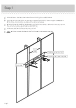
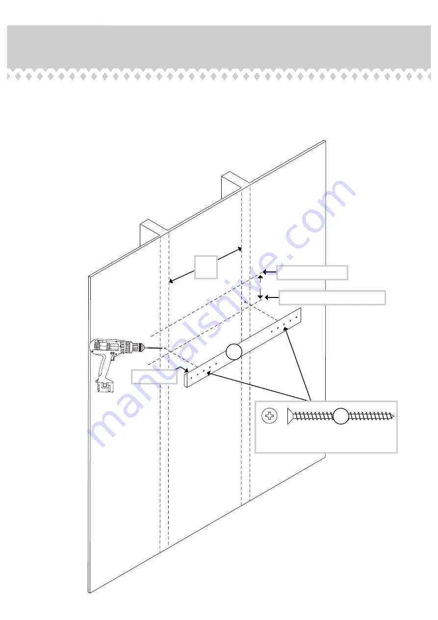
Drill a 1/8" hole in your wall at each wall stud location.

 å

Fasten the WALL SUPPORT (A) to your wall using two
SILVER 2" FLAT HEAD SCREWS (4) into the 1/8" holes. 

7"

Upper line of wall unit

Lower line of WALL SUPPORT (A)

Wall 
Stud

SILVER 2" FLAT HEAD SCREW

(2 used in this step)

4

A

Angled edge

Page 5

Summary of Contents for 5423547

Page 1: ...www teknikoffice co uk Avon Leather Handled Wall Desk Model 5423547 For things n such Teknik ...

Page 2: ...cation Assembly Steps Français Español Safety Warranty 3 3 4 9 10 11 12 13 14 15 No 2 Phillips Screwdriver Tip Shown Actual Size Electric drill with 1 8 and 3 16 or 6mm bits ONLY in indicated step Pencil Tape Measure Level Page 2 Hammer Table of Contents Assembly Tools Required ...

Page 3: ...sh similar parts from each other Use this part identification to help identify similar parts Now you know our ABCs A WALL SUPPORT 1 B WALL UNIT 1 A B Page 3 www sauder 423547 DRYWALL ANCHOR 2 2 SILVER 2 FLAT HEAD SCREW 2 4 METAL BRACKET 2 1 SILVER 1 3 8 FLAT HEAD SCREW 2 5 L WRENCH 1 3 SILVER 1 2 HEX HEAD SCREW 2 6 Hardware Identification ...

Page 4: ...ructions provided with the anchoring hardware å Determine the desired height of the Wall Desk on your wall and subtract 7 Mark this location on your wall This will be the bottom edge of the WALL SUPPORT A å Locate and mark the wall stud locations on your wall å NOTE BE SURE THE TWO MARKS ON THE STUDS ARE LEVEL BEFORE DRILLING 7 Desired upper line of wall unit Lower edge line of WALL SUPPORT Wall S...

Page 5: ...h wall stud location å Fasten the WALL SUPPORT A to your wall using two SILVER 2 FLAT HEAD SCREWS 4 into the 1 8 holes 7 Upper line of wall unit Lower line of WALL SUPPORT A Wall Stud SILVER 2 FLAT HEAD SCREW 2 used in this step 4 A Angled edge Page 5 ...

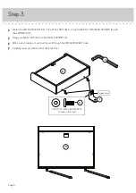
Page 6: ... HEAD SCREWS 6 with the L WRENCH 3 å Hang your WALL UNIT B onto the WALL SUPPORT A å With a pencil create a mark onto the wall through the METAL BRACKET holes å Carefully lower your WALL UNIT B to the floor B Page 6 B SILVER 1 2 FLAT HEAD SCREW 2 used in this step 6 1 larger hole 3 ...

Page 7: ...or 1 8 hole into a stud in the wall å 2 Gently tap a DRYWALL ANCHOR 2 into each hole until it is flush with the wall å NOTE Stud attachment will not use a DRYWALL ANCHOR 2 1 Drill an 3 16 or 6mm hole for the DRYWALL ANCHOR Drill an 1 8 hole into a stud in the wall 2 Wall Stud Page 7 ...

Page 8: ...LL SUPPORT å Fasten the WALL UNIT B to the wall by turning two SILVER 1 3 8 FLAT HEAD SCREWS 5 through the METAL BRACKETS and into the DRYWALL ANCHORS or stud in the wall Step 5 SILVER 1 3 8 FLAT HEAD SCREW 2 used in this step 5 B Page 8 ...

Page 9: ...ase read the back pages of the instruction booklet for important safety information å This completes assembly Clean with your favorite furniture polish or a damp cloth Wipe dry Step 6 10 lbs 10 lbs 25 lbs Page 9 ...

Page 10: ...injury and damage Carefully review and follow the mounting instructions contained in this manual Overloaded shelves Risk of injury or property damage Overloaded furniture can break Never exceed the weight limits shown in the instructions Improper use of furniture to support TV s Placing TV s on furniture items not intended to support them is hazardous Risk of injury or death TV s can be very heavy...

Reviews: