background image

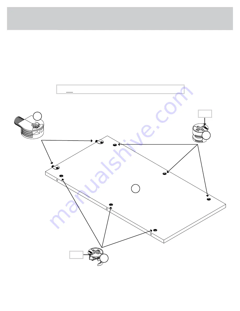
Step 19

Page 25

1F

Arrow

1F

Arrow

 å

Push two SAUDER TWIST-LOCK® FASTENERS (12F) into the

large holes in the BACK (O).

 å

Push six HIDDEN CAMS (1F) into the BACK (O).

12F

Do not tighten the TWIST-LOCK® FASTENERS in this step.

O

Summary of Contents for 5427718

Page 1: ...NOTE THIS INSTRUCTION BOOKLET CONTAINS IMPORTANT SAFETY INFORMATION PLEASE READ AND KEEP FOR FUTURE REFERENCE White Home Study L Shaped Desk Model 5427718 Sit and surf Teknik www teknikoffice co uk ...

Page 2: ...her Use this part identification to help identify similar parts A RIGHT END 1 B LEFT END 1 C SMALL TOP 1 D LARGE TOP 1 D32 LARGE LEFT DRAWER SIDE 1 D33 LARGE RIGHT DRAWER SIDE 1 D53 SMALL RIGHT DRAWER SIDE 1 D59 SMALL LEFT DRAWER SIDE 1 D78 LARGE DRAWER BACK 1 D109 SMALL DRAWER BACK 1 D707 SMALL DRAWER BOTTOM 1 D708 LARGE DRAWER BOTTOM 1 E LEFT UPRIGHT 1 F LEFT FRONT LEG 3 G RIGHT FRONT LEG 3 H CO...

Page 3: ...Part Identification Page 3 A B C D E F G H J K L M N O P Q R S T U D33 D707 F G F G D708 D32 D78 D59 D53 D109 Now you know our ABCs ...

Page 4: ...PARATED EXTENSION SLIDE 2 45MC EXTENSION RAIL 2 45MA FILE GLIDE 2 5B FILE ROD 2 8B HIDDEN CAM 30 1F CAM SCREW 30 8F 12F TWIST LOCK FASTENER 27 WOOD DOWEL 11 15F ANGLE BRACKET 7 5G SMALL DRAWER FRONT BRACKET 1 7G LARGE DRAWER FRONT BRACKET 2 10G PLATE 3 41G KNOB 2 111K GROMMET CAP 2 1P GROMMET 2 10P SCREW COVER 6 17P CAM COVER 18 19P ...

Page 5: ...ve extra hardware with your unit Page 5 BLACK 9 16 LARGE HEAD SCREW 32 1S 3S GOLD 5 16 FLAT HEAD SCREW 16 SILVER 1 1 8 FLAT HEAD SCREW 4 10S 30S BLACK 1 9 16 FLAT HEAD SCREW 8 SILVER 1 2 MACHINE SCREW 1 38S GOLD 1 MACHINE SCREW 1 50S BLACK 1 15 16 FLAT HEAD SCREW 5 113S ...

Page 6: ...driver as tight as possible Dowel end 2 Push a TWIST LOCK FASTENER into the large hole in the part 1 HOW TO USE A TWIST LOCK FASTENER Cam Screw Hidden Cam Arrow Push a HIDDEN CAM into the part The arrow in the HIDDEN CAM must point toward the hole in the edge of the board Hole 2 3 1 2 Insert the CAM SCREW into the HIDDEN CAM Tighten the HIDDEN CAM HOW TO USE A HIDDEN CAM CAM SCREW Turn the CAM SCR...

Page 7: ...floor or on the empty carton to avoid scratching your unit or the floor å To begin assembly push two SAUDER TWIST LOCK FASTENERS 12F into the large holes in the RIGHT END A å Insert one WOOD DOWEL 15F into the RIGHT END A Page 7 A 12F Do not tighten the TWIST LOCK FASTENERS in this step 15F ...

Page 8: ...å Push six HIDDEN CAMS 1F into the RIGHT END A å Turn six CAM SCREWS 8F into the LEGS F and G Step 2 Page 8 A F G 8F 1F Arrow 1F Arrow ...

Page 9: ...LEGS F and G to the RIGHT END A Tighten six HIDDEN CAMS å NOTE Be sure the WOOD DOWELS in the LEGS insert into the END Step 3 Page 9 F G A These surfaces should be even 15F The LEGS will overhang this edge Surface with HIDDEN CAMS Edge with TWIST LOCK FASTENERS 15F ...

Page 10: ...å Push six SAUDER TWIST LOCK FASTENERS 12F into the large holes in the LARGE MODESTY PANEL J Step 4 Page 10 12F Do not tighten the TWIST LOCK FASTENERS in this step J 12F ...

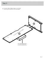
Page 11: ...å Fasten the LARGE MODESTY PANEL J to the RIGHT END A Tighten three TWIST LOCK FASTENERS Step 5 Page 11 A Surface with TWIST LOCK FASTENERS J For support place packing foam and magazines here ...

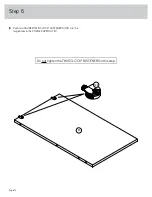
Page 12: ...Step 6 Page 12 å Push two SAUDER TWIST LOCK FASTENERS 12F into the large holes in the CORNER UPRIGHT H H 12F Do not tighten the TWIST LOCK FASTENERS in this step ...

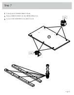
Page 13: ...Step 7 Page 13 å Carefully turn the CORNER UPRIGHT H over å Push six HIDDEN CAMS 1F into the CORNER UPRIGHT H å Turn six CAM SCREWS 8F into the LEGS F and G H F G 8F 1F Arrow 1F Arrow ...

Page 14: ...asten the LEGS F and G to the CORNER UPRIGHT H Tighten six HIDDEN CAMS å NOTE Be sure the WOOD DOWELS in the LEGS insert into the UPRIGHT F G H These surfaces should be even 15F The LEGS will overhang this edge Surface with HIDDEN CAMS Edge with TWIST LOCK FASTENERS 15F ...

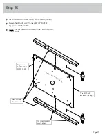
Page 15: ... HEAD SCREWS 10S å NOTE You should start each SCREW a few turns before completely tightening any of them å NOTE Do not overtighten the SCREWS into the UPRIGHT Step 9 Page 15 H Surface with HIDDEN CAMS J SILVER 1 1 8 FLAT HEAD SCREW 4 used in this step 10S Edge with TWIST LOCK FASTENERS ...

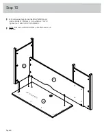
Page 16: ...ne s help fasten the RIGHT END A and LARGE MODESTY PANEL J to the SMALL TOP C Tighten four TWIST LOCK FASTENERS å NOTE Be sure the WOOD DOWEL in the END inserts into the TOP Step 10 Page 16 Surface with holes J C A ...

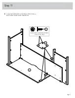
Page 17: ...å Fasten the PLATES 41G to the SMALL TOP C Use six BLACK 9 16 LARGE HEAD SCREWS 1S Step 11 Page 17 41G BLACK 9 16 LARGE HEAD SCREW 6 used in this step 1S C ...

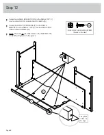
Page 18: ...he LONG TOP MOLDING P to the ANGLE BRACKETS on the SMALL TOP C Use four BLACK 9 16 LARGE HEAD SCREWS 1S å NOTE There are no pre drilled holes in the M0LDING The SCREWS will tighten into the groove Step 12 Page 18 BLACK 9 16 LARGE HEAD SCREW 8 used in this step 1S 5G The groove is closer to this edge C P ...

Page 19: ...rt two WOOD DOWELS 15F into the LEFT END B and LEFT UPRIGHT E å Push four SAUDER TWIST LOCK FASTENERS 12F into the large holes in the LEFT END B and LEFT UPRIGHT E 12F Do not tighten the TWIST LOCK FASTENERS in this step 15F 15F ...

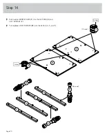
Page 20: ...å Push twelve HIDDEN CAMS 1F into the LEFT END B and LEFT UPRIGHT E å Turn eighteen CAM SCREWS 8F into the LEGS F G S and T Step 14 Page 20 8F 1F Arrow 1F Arrow 8F 8F B E F S T G 18 used 12 used ...

Page 21: ...GS G and T to the LEFT UPRIGHT E Tighten six HIDDEN CAMS å NOTE Be sure the WOOD DOWELS in the LEGS insert into the UPRIGHT T G E These surfaces should be even 15F The LEGS will overhang this edge Surface with HIDDEN CAMS Edge with TWIST LOCK FASTENERS 15F The CAM SCREWS must be here ...

Page 22: ...e LEGS F and S to the LEFT END B Tighten six HIDDEN CAMS å NOTE Be sure the WOOD DOWELS in the LEGS insert into the END S F B These surfaces should be even 15F The LEGS will overhang this edge Surface with HIDDEN CAMS Edge with TWIST LOCK FASTENERS 15F The CAM SCREWS must be here ...

Page 23: ...For each EXTENSION RAIL turn a SCREW into the hole shown in the enlarged diagram Then slide the inner cartridge of the EXTENSION RAIL in to find the other hole that lines up with the hole in the END and UPRIGHT Turn a SCREW into this hole å NOTE The EXTENSION SLIDES will be used later for the LARGE DRAWER Open end Open end Push the black lever in and pull the SLIDE from the RAIL 45MA 45MC 3 2 1 1 ...

Page 24: ... 3S through holes 1 and 4 å Fasten the CABINET LEFT 45BB to the LEFT END B Use two GOLD 5 16 FLAT HEAD SCREWS 3S through holes 1 and 4 Step 18 Page 24 1 3 2 1 3 2 Roller end 4 4 45BB 45BB B E Roller end The CAM SCREWS must be here 45BA 45BA GOLD 5 16 FLAT HEAD SCREW 4 used for the RAILS 3S ...

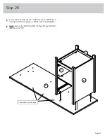
Page 25: ...19 Page 25 1F Arrow 1F Arrow å Push two SAUDER TWIST LOCK FASTENERS 12F into the large holes in the BACK O å Push six HIDDEN CAMS 1F into the BACK O 12F Do not tighten the TWIST LOCK FASTENERS in this step O ...

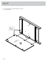
Page 26: ...å Fasten the BACK O to the RIGHT REAR LEG T Tighten three HIDDEN CAMS Step 20 Page 26 O T Edge with TWIST LOCK FASTENERS Surface with HIDDEN CAMS ...

Page 27: ...Step 21 Page 27 å Push eight SAUDER TWIST LOCK FASTENERS 12F into the large holes in the SHELF L and BOTTOM M 12F Do not tighten the TWIST LOCK FASTENERS in this step 12F L M ...

Page 28: ...MOLDING R onto the notched edge of the BOTTOM M å U S Patent No 5 499 886 Slide the BOTTOM MOLDING R onto the notched edge These surfaces should be even The groove is closer to this edge Notched edge Surface with TWIST LOCK FASTENERS M R ...

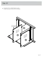
Page 29: ...å Fasten the SHELF L and BOTTOM M to the LEFT UPRIGHT E Tighten four TWIST LOCK FASTENERS Step 23 Page 29 L E Surface with TWIST LOCK FASTENERS M Surface with TWIST LOCK FASTENERS Finished edge ...

Page 30: ...å Fasten the LEFT END B to the SHELF L and BOTTOM M Tighten four TWIST LOCK FASTENERS å Fasten the LEFT REAR LEG S to the BACK O Tighten three HIDDEN CAMS Step 24 Page 30 O L M B S 2 1 ...

Page 31: ...e LEFT END B LEFT UPRIGHT E and BACK O to the LARGE TOP D Tighten six TWIST LOCK FASTENERS å NOTE Be sure the WOOD DOWELS in the END and UPRIGHT insert into the TOP Step 25 Page 31 E B D O These holes must be here ...

Page 32: ...Step 26 Page 32 å Push three SAUDER TWIST LOCK FASTENERS 12F into the large holes in the SMALL MODESTY PANEL K Do not tighten the TWIST LOCK FASTENERS in this step K 12F ...

Page 33: ...ten the SMALL MODESTY PANEL K to the LEFT UPRIGHT E Use three BLACK 1 15 16 FLAT HEAD SCREWS 113S å NOTE You should start each SCREW a few turns before completely tightening any of them Step 27 Page 33 K D E Surface with TWIST LOCK FASTENERS BLACK 1 15 16 FLAT HEAD SCREW 3 used in this step 113S ...

Page 34: ...WS 1S å Fasten the SHORT TOP MOLDING Q to the ANGLE BRACKETS on the LARGE TOP D Use three BLACK 9 16 LARGE HEAD SCREWS 1S å NOTE There are no pre drilled holes in the M0LDING The SCREWS will tighten into the groove BLACK 9 16 LARGE HEAD SCREW 6 used in this step 1S 5G The groove is closer to this edge D Q ...

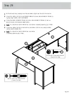
Page 35: ... PANEL J Use two BLACK 1 15 16 FLAT HEAD SCREWS 113S å NOTE You should start each SCREW a few turns before completely tightening any of them å Fasten the LARGE TOP D to the PLATES on the SMALL TOP C Use six BLACK 9 16 LARGE HEAD SCREWS 1S å NOTE You should start each SCREW a few turns before completely tightening any of them Step 29 Page 35 BLACK 9 16 LARGE HEAD SCREW 6 used in this step 1S BLACK ...

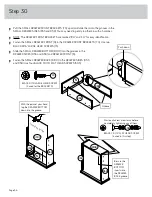
Page 36: ...707 into the grooves in the DRAWER SIDES D53 and D59 and DRAWER FRONT N å Fasten the SMALL DRAWER BACK D109 to the DRAWER SIDES D53 and D59 Use four BLACK 1 9 16 FLAT HEAD SCREWS 30S Step 30 Page 36 D707 D53 D109 N D59 D53 D59 D53 D59 Groove Unfinished surface Be sure the DRAWER BOTTOM inserts into the DRAWER BACK groove 30S Start each screw a few turns before completely tightening any of them BLA...

Page 37: ...IDE D59 Use two GOLD 5 16 FLAT HEAD SCREWS 3S through holes 2 and 4 å Fasten one KNOB 111K to the SMALL DRAWER FRONT N Use one GOLD 1 MACHINE SCREW 50S Step 31 Page 37 1 3 2 4 1 3 2 4 GOLD 5 16 FLAT HEAD SCREW 4 used for the SLIDES 3S Drawer Slide Center the screw in the oval hole 45BC 45BC 45BD 45BD Roller end D53 N D59 111K GOLD 1 MACHINE SCREW 1 used for the KNOB 50S Roller end ...

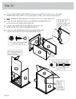
Page 38: ... grooves in the DRAWER SIDES D32 and D33 and DRAWER FRONT U å Fasten the LARGE DRAWER BACK D78 to the DRAWER SIDES D32 and D33 Use four BLACK 1 9 16 FLAT HEAD SCREWS 30S D708 D33 U D32 D33 D32 D33 D32 Groove Unfinished surface Be sure the DRAWER BOTTOM inserts into the DRAWER BACK groove 30S Start each screw a few turns before completely tightening any of them BLACK 1 9 16 FLAT HEAD SCREW 4 used i...

Page 39: ...ugh holes 2 and 4 å Fasten one KNOB 111K to the LARGE DRAWER FRONT U Use one SILVER 1 2 MACHINE SCREW 38S Step 33 Page 39 Open end GOLD 5 16 FLAT HEAD SCREW 4 used for the SLIDES 3S Drawer Slide Center the screw in the oval hole 1 2 3 4 1 2 3 4 D33 U D32 Open end 111K SILVER 1 2 MACHINE SCREW 1 used for the KNOB 38S ...

Page 40: ...DE 5B on the LARGE RIGHT DRAWER SIDE å Slide another FILE GLIDE 5B onto the other end of the FILE RODS 8B then press this FILE GLIDE over the LARGE LEFT DRAWER SIDE D32 Step 34 Page 40 Insert the FILE RODS into the holes of your choice in the FILE GLIDES depending on your file sizes D33 D32 5B 8B 5B 8B ...

Page 41: ...N SLIDES on the drawer with the EXTENSION RAILS on the unit and push the drawer into the unit until the drawer is fully inserted The drawer will push in hard until it is all the way in then it will slide in and out easier Step 35 Page 41 1P 10P C D Place the roller on the SLIDE behind the roller on the RAIL Adjust the drawer up or down Drawer Slide To adjust the DRAWER FRONT using the DRAWER SLIDE...

Page 42: ...tap in with your hammer å Using your hammer gently tap a CAM COVER 19P onto each visible HIDDEN CAM å NOTE Please read the back pages of the instruction booklet for important safety information å This completes assembly Clean with a damp cloth Wipe dry Step 36 Page 42 17P 19P ...

Page 43: ... moving furniture that is not designed and equipped with casters Furniture can tip over or break if improperly moved Physical injury Furniture can be very heavy Breakage of tops particularly with double pedestal furniture drawers at both ends Unload shelves and drawers from top to bottom before moving the unit Do not push furniture especially on a carpeted floor Have a friend help you lift the ite...

Page 44: ...to con ruedecitas La inclinación o rotura del mobiliario es posible si se mueve de manera inadecuada Lesión física El mobiliario puede ser muy pesado Rotura de las superficies especialmente las unidades con dos pedestales con cajones en cada extremo Descargue los estantes y cajones desde arriba hacia abajo antes de mover la unidad No empuje la unidad especialmente sobre un piso alfombrado Pide la ...

Page 45: ...de rechange seront garanties uniquement pendant la période restante de la garantie originale SAUDER NE SERA EN AUCUN CAS RESPONSABLE de TOUT DOMMAGE ACCESSOIRE OU CONSÉCUTIF DE TOUTE SORTE et lesdits dommages sont EXCLUS DE LA PRÉSENTE GARANTIE à savoir perte d utilisation démontage transport main d œuvre ou dommages matériels sur ou à proximité du produit Certains États ou provinces ne permettant...

Page 46: ...product and view Sauder products www sauder com service So how did it go Set a world record for speed Feeling good about yourself Nice Get social with it on any of these quality share sites And don t forget to rate and review your piece at Sauder com in the product detail page Dear Valued Customer Thanks so much for choosing Sauder furniture I hope the purchase and assembly process was a positive ...

Reviews: