background image

Table of Contents

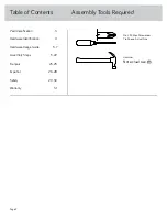
Assembly Tools Required

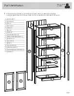
Part Identification

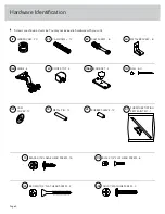
Hardware Identification

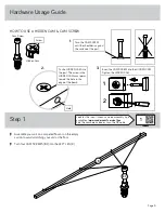
Hardware Usage Guide

Assembly Steps

Français

Español

Safety

Warranty

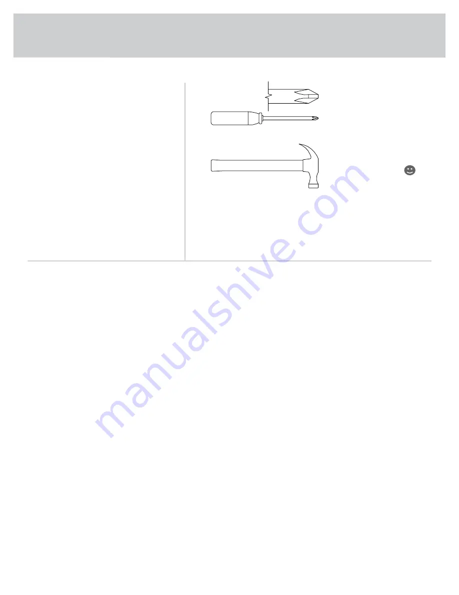
Hammer

Not actual size 

No. 2 Phillips Screwdriver

Tip Shown Actual Size

3

4

5, 7

5-22

23-25

26-28

29-30

31

Page 2

Summary of Contents for 5431262

Page 1: ...NSTRUCTION BOOKLET CONTAINS IMPORTANT SAFETY INFORMATION PLEASE READ AND KEEP FOR FUTURE REFERENCE Shaker Style Bookcase with Doors Raven Oak Model 5431262 Here s one for the books Teknik www teknikof...

Page 2: ...Required Part Identification Hardware Identification Hardware Usage Guide Assembly Steps Fran ais Espa ol Safety Warranty Hammer Not actual size No 2 Phillips Screwdriver Tip Shown Actual Size 3 4 5 7...

Page 3: ...her Use this part identification to help identify similar parts Now you know our ABCs Page 3 A RIGHT END 1 B LEFT END 1 C2 TOP 1 D BOTTOM 1 E SHELF 1 F BACK 1 G DOOR 2 H ADJUSTABLE SHELF 2 I SMALL ADJ...

Page 4: ...HEAD SCREW 16 1S BLACK 1 2 FLAT HEAD SCREW 8 11S CAM SCREW 8 8F HIDDEN CAM 20 1F CAM DOWEL 12 2F GOLD 1 MACHINE SCREW 2 50S BROWN 1 1 2 FLAT HEAD SCREW 2 14S METAL BRACKET 8 4G METAL PIN 12 1R RUBBER...

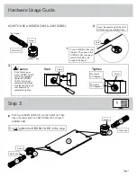
Page 5: ...HIDDEN CAM HOW TO USE A HIDDEN CAM CAM SCREW Turn the CAM SCREW until the shoulder is against the surface of the part 1 Look for this icon It means a video assembly tip is available at www sauder com...

Page 6: ...F into the LEFT END B Fasten the LEFT LEG K to the LEFT END B Tighten four HIDDEN CAMS 1F Arrow 1F Arrow B Surface with HIDDEN CAMS K Edge with HIDDEN CAMS These surfaces should be even B Page 6 Some...

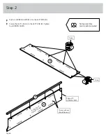
Page 7: ...he board Hole Arrow Metal end Hidden Cam Cam Dowel Start Tighten Arrow Minimum 190 degrees Caution Risk of damage or injury HIDDEN CAMS must be completely tightened HIDDEN CAMS that are not completely...

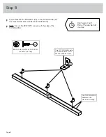
Page 8: ...SHELF E to the LEFT END B Tighten two HIDDEN CAMS Slide the SHELF MOLDING N onto the notched edge of the SHELF E U S Patent No 5 499 886 B K Surface with HIDDEN CAMS E N Surface with HIDDEN CAMS Slid...

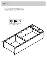
Page 9: ...e RIGHT LEG J Push six HIDDEN CAMS 1F into the RIGHT END A Fasten the RIGHT LEG J to the RIGHT END A Tighten four HIDDEN CAMS A J 8F 1F Arrow 1F Arrow A J Surface with HIDDEN CAMS Edge with HIDDEN CAM...

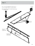
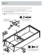
Page 10: ...DOWEL 2F into each HIDDEN CAM Fasten the BOTTOM D to the LEFT END B Tighten two HIDDEN CAMS Fasten the RIGHT END A to the BOTTOM D and SHELF E Tighten four HIDDEN CAMS B E D A J Surface without HIDDEN...

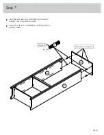
Page 11: ...7 Insert the metal end of a CAM DOWEL 2F into each HIDDEN CAM in the ENDS A and B Fasten the TOP C2 to the ENDS A and B Tighten four HIDDEN CAMS Page 11 B A C2 These holes must be here Metal end 2F 4...

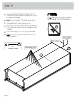
Page 12: ...CREWS 1S NOTE Be sure the BRACKETS are even with the edge of the TOP MOLDING 4G M BLACK 9 16 LARGE HEAD SCREW 3 used in this step 1S The TOP MOLDING hole must be centered in this METAL BRACKET hole Th...

Page 13: ...Page 13 Fasten the TOP MOLDING M to the TOP C2 Use three BLACK 9 16 LARGE HEAD SCREWS 1S through the METAL BRACKETS on the TOP MOLDING and into the TOP BLACK 9 16 LARGE HEAD SCREW 3 used in this step...

Page 14: ...SPACER P Fasten five METAL BRACKETS 4G to the ENDS A and B and BOTTOM D Use five BLACK 9 16 LARGE HEAD SCREWS 1S NOTE Be sure the BRACKETS are even with the edges of the ENDS and BOTTOM E E P 4I BROW...

Page 15: ...er onto its front edges Fasten the BASE L to the ENDS A and B and BOTTOM D Use five BLACK 9 16 LARGE HEAD SCREWS 1S through the METAL BRACKETS on the ENDS and BOTTOM and into the BASE BLACK 9 16 LARGE...

Page 16: ...AFETY STRAP exactly as shown Unfold the BACK F and lay it over your unit Make equal margins along all four edges of the BACK F Push on opposite corners of your unit if needed to make it square Fasten...

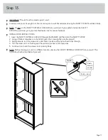
Page 17: ...the SAFETY DRYWALL ANCHOR through the WASHER and the end of the SAFETY STRAP 2 Using a Phillips screwdriver or a hand drill press the screw slightly onto the drywall 3 Apply pressure turn the screw u...

Page 18: ...Step 14 Page 18 14H 14H BLACK 1 2 FLAT HEAD SCREW 8 used in this step 11S Fasten four HINGES 14H to the DOORS G Use eight BLACK 1 2 FLAT HEAD SCREWS 11S G G...

Page 19: ...ting screw Fasten one of the DOORS G to the LEFT END B as shown in the lower diagram Use the screws in the HINGES You should start each SCREW a few turns before completely tightening any of them Faste...

Page 20: ...n the adjusting screw in or out To adjust the DOORS up and down vertical loosen both vertical adjustment screws Move the DOORS up or down to the desired location Tighten the screws after making adjust...

Page 21: ...the notched edge of an ADJUSTABLE SHELF H Repeat this step for the other ADJUSTABLE SHELF H U S Patent No 5 499 886 Slide the ADJUSTABLE SHELF MOLDING O onto the notched edge O H The groove is closer...

Page 22: ...et the ADJUSTABLE SHELVES H and I onto the METAL PINS Using your hammer gently tap a CAM COVER 12P onto each visible HIDDEN CAM NOTE Please read the back pages of the instruction booklet for important...

Page 23: ...break if improperly moved Physical injury Furniture can be very heavy Unload shelves from top to bottom before moving the furniture Do not push furniture especially on a carpeted floor Have a friend h...

Reviews: