background image

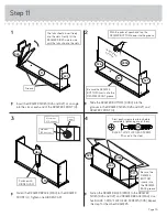
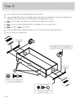
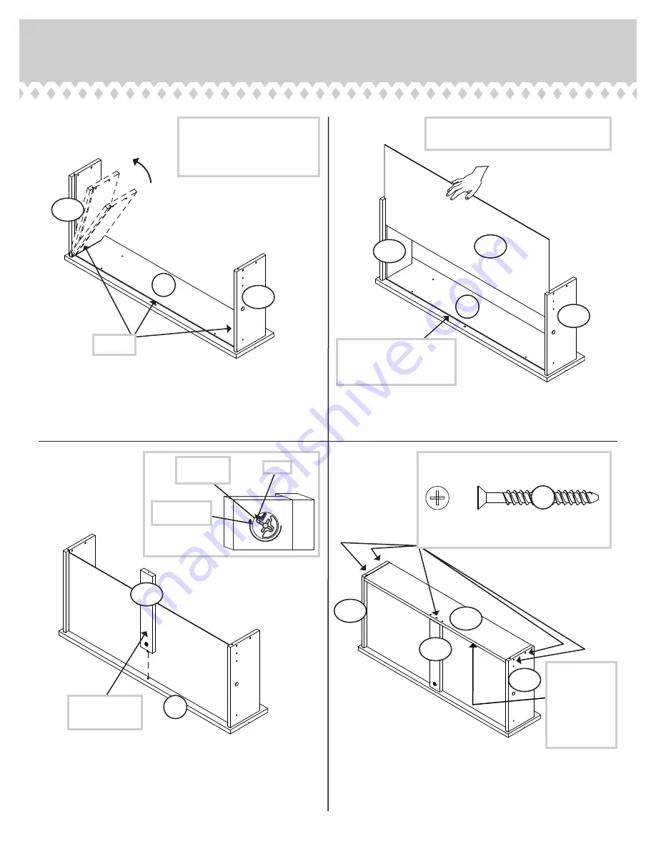
Step 11

Page 15


å

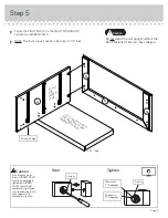
Insert the DRAWER SIDES (D26 and D27) at an angle 
into the slot at each end of the DRAWER FRONT (H).


å

Slide the DRAWER BOTTOM (D994) into the 
grooves in the DRAWER SIDES (D26 and D27) and 
DRAWER FRONT (H). 


å

Fasten the DRAWER BRACE (M64) to the DRAWER 
FRONT (H). Tighten one HIDDEN CAM. 


å

Fasten the DRAWER BACK (D189) to the DRAWER 
SIDES (D26 and D27) and DRAWER BRACE (M64). Use 
five BLACK 1-9/16" FLAT HEAD SCREWS. (30S). Repeat 
this step for the other DRAWERS. 

1

2

3

4

Be sure the DRAWER 
BOTTOM inserts into the 
DRAWER FRONT groove.

With the palm of your hand, tap the 
DRAWER BOTTOM down into the groove. 

Groove

Arrow

Maximum
210 degrees

Minimum
190 degrees

H

H

H

D27

D26

D27

D994

D26

D26

D27

D189

Unfi

 nished 

sur

face

Be sure the 
DRAWER 
BOTTOM 
inserts into 
the DRAWER 
BACK groove.

30S

Start each screw a few turns before 

completely tightening any of them.

BLACK 1-9/16" FLAT HEAD SCREW

(15 used in this step)

The tabs should insert freely 
into the slots. Gently tilt the 
DRAWER SIDES side to side 
until the tabs slip into the slots.

M64

M64

Surface with 
HIDDEN CAM

Summary of Contents for Barrister Home 3 Drawer Chest 5418702

Page 1: ...TRUCTION BOOKLET CONTAINS IMPORTANT SAFETY INFORMATION PLEASE READ AND KEEP FOR FUTURE REFERENCE Barrister Home 3 Drawer Chest Barrister Home Collection Model 5418702 For things n such Teknik www teknikoffice co uk ...

Page 2: ... your TV Compare it to the diagram to the right before you begin assembly This Sauder unit is designed for use with televisions weighing less than 50 pounds Never use with a TV that weighs more The size of the television front to back and side to side must fit within the space defined in the diagram Never place the front edge of the TV past the front edge of the TV support shelf or stop molding if e...

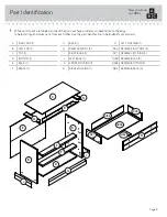
Page 3: ...ation to help identify similar parts A RIGHT END 1 B LEFT END 1 C TOP 1 D BOTTOM 1 E BACK 1 F BRACE 2 G BASE 1 H DRAWER FRONT 3 I RIGHT BASE 1 J LEFT BASE 1 K FRONT MOLDING 1 N RIGHT MOLDING 1 O LEFT MOLDING 1 D26 DRAWER RIGHT SIDE 3 D27 DRAWER LEFT SIDE 3 D189 DRAWER BACK 3 D994 DRAWER BOTTOM 3 M64 DRAWER BRACE 3 Now you know our ABCs Page 3 N O A B C D E F G H I J K M64 D994 D26 D27 D189 F ...

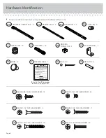
Page 4: ...te safety information Note This is a permanent label Do not try to remove Surface will be damaged 08 05 2 6 9 2 2 0 269220 WARNING LABEL 1 1L Refer to Step 13 for proper location and application 35AA UNIVERSAL CABINET RAIL 6 35AC DRAWER RIGHT 3 35AD DRAWER LEFT 3 METAL BRACKET 7 4G BLACK 9 16 LARGE HEAD SCREW 14 1S SILVER 1 1 8 FLAT HEAD SCREW 7 10S BLACK 1 1 4 FLAT HEAD SCREW 4 7S BLACK 7 8 MACHI...

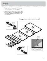
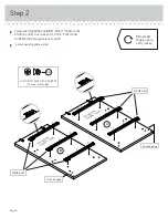
Page 5: ...h fifteen HIDDEN CAMS 1F into the ENDS A and B BOTTOM D BRACES F and DRAWER BRACES M64 Then insert the metal end of a CAM DOWEL 2F into each HIDDEN CAM Page 5 Arrow 1F 2F 15 used Arrow 1F 2F Do not tighten the HIDDEN CAMS in this step Insert the metal end of the CAM DOWEL into the HIDDEN CAM Arrow A B D F M64 F M64 M64 ...

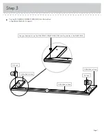
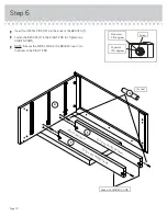
Page 6: ...S 3S through holes 1 and 3 å patent pending glide system GOLD 5 16 FLAT HEAD SCREW 12 used in this step 3S 3 2 1 1 2 3 A 1 2 3 1 2 3 3 2 1 3 2 1 Glide end Glide end Finished edge S u r f a c e w i t h H I D D E N C A M S B S u r f a c e w i t h H I D D E N C A M S Finished edge Remember Righty tighty Lefty loosey ...

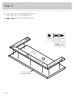
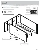
Page 7: ... 19F into the notches in the MOLDINGS K N and O Step 3 Page 7 Use your hammer to tap the MOLDING CONNECTORS 19F into the notches in the MOLDINGS Flat end Flat end 19F N O K 19F Unfinished surface Unfinished surface Unfinished surface ...

Page 8: ...10S å NOTE Do not overtighten the SCREWS into the TOP N O C K F i n i s h e d s u r f a c e F i n i s h e d s u r f a c e S u r f a c e w i t h h o l e s F i n i s h e d s u r f a c e SILVER 1 1 8 FLAT HEAD SCREW 7 used in this step 10S Do not overtighten the SCREWS 10S Long curved edge Page 8 ...

Page 9: ...the unit upright without the BACK fastened The unit may collapse Caution Start Tighten Arrow Minimum 190 degrees Caution Risk of damage or injury HIDDEN CAMS must be completely tightened HIDDEN CAMS that are not completely tightened may loosen and parts may separate To completely tighten Arrow Maximum 210 degrees F o r s u p p o r t p l a c e p a c k i n g f o a m a n d m a g a z i n e s h e r e 1...

Page 10: ...e RIGHT END A Tighten two HIDDEN CAMS å NOTE Be sure the METAL PINS in the BRACES insert into the holes in the RIGHT END Step 6 Page 10 A F F Surface with HIDDEN CAMS Surface with HIDDEN CAMS 1R 4 used Arrow Minimum 190 degrees Maximum 210 degrees Edge with HIDDEN CAMS F o a m s u p p o r t ...

Page 11: ...RIGHT END A Tighten two HIDDEN CAMS Arrow Minimum 190 degrees Maximum 210 degrees A D Surface with HIDDEN CAMS These holes must be here For support place packing foam and magazines here If you re doing this to help a friend don t leave without a bite ...

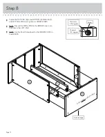
Page 12: ...en six HIDDEN CAMS å NOTE Be sure the METAL PINS in the BRACES insert into the holes in the LEFT END å NOTE Use the Short Screwdriver for the HIDDEN CAMS in the BRACES Step 8 Arrow Minimum 190 degrees Maximum 210 degrees B Surface without HIDDEN CAMS D F F Finished edge Page 12 O ...

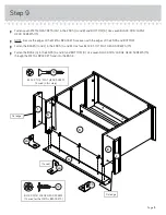
Page 13: ...å Fasten the BASES I and J to the ENDS A and B Use four BLACK 1 1 4 FLAT HEAD SCREWS 7S å Fasten the BASE G to the ENDS A and B and BOTTOM D Use seven BLACK 9 16 LARGE HEAD SCREWS 1S through the METAL BRACKETS and into the BASE Step 9 B A D G I J BLACK 9 16 LARGE HEAD SCREW 14 used for the METAL BRACKETS 1S 4G 7 used BLACK 1 1 4 FLAT HEAD SCREW 4 used in this step 7S Flat edge Page 13 Flat edge 4G...

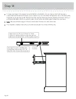
Page 14: ...along all four edges of the BACK E Push on opposite corners of your unit if needed to make it square å Fasten the BACK E to your unit using the NAILS 1N Do not stand the unit upright without the BACK fastened The unit may collapse Caution NAIL 30 used in this step 1N E Page 14 ...

Page 15: ...this step for the other DRAWERS 1 2 3 4 Be sure the DRAWER BOTTOM inserts into the DRAWER FRONT groove With the palm of your hand tap the DRAWER BOTTOM down into the groove Groove Arrow Maximum 210 degrees Minimum 190 degrees H H H D27 D26 D27 D994 D26 D26 D27 D189 Unfinished surface Be sure the DRAWER BOTTOM inserts into the DRAWER BACK groove 30S Start each screw a few turns before completely tig...

Page 16: ...hole in the SLIDE å NOTE The parts are marked DRAWER RIGHT and DRAWER LEFT for easy identification å NOTE The glides are not intended to rotate å Fasten four KNOBS 71K to the DRAWER FRONT H Use four BLACK 7 8 MACHINE SCREWS 37S å Repeat this step for the other drawers Screw head turn CAM to line up holes in the SLIDES with holes in DRAWER SIDES 10A 10A 1 2 1 2 H D26 D27 BLACK 7 8 MACHINE SCREW 12 u...

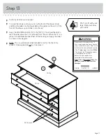
Page 17: ...wn in the diagram å NOTE This is a permanent label intended to last for the life of the product Once applied do not try to remove it Step 13 Page 17 50 lbs 30 lbs 30 lbs each WARNING Never use this furniture with a TV that is too large or too heavy Severe injury or death can occur The TV and furniture will be unstable and may tip The TV must weigh less than 50 lbs The base of the TV must be able t...

Page 18: ...elp the DRAWER FRONTS line up better when closed Tighten the SCREW when finished with adjustments å NOTE Please read the back pages of the instruction booklet for important safety information å This completes assembly Clean with your favorite furniture polish or a damp cloth Wipe dry The higher the screw in the oblong hole the higher your drawer front will be The lower the screw the lower the drawe...

Page 19: ...limbing on a piece of furniture can make it top heavy and cause it to tip over Never allow children to climb on or play with furniture Do not place toys food etc on the top shelves or upper drawers Placing TVs on furniture items that are not designed to support a television is hazardous Risk of injury or death TVs can be heavy and the location of the picture tube tends to make TVs unbalanced and p...

Reviews: