background image

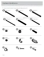
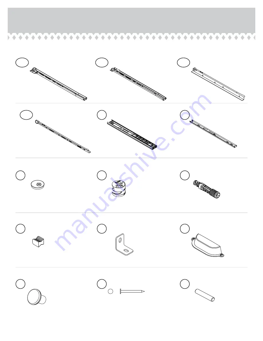
Hardware Identifi cation


å

Screws are shown actual size. You may receive extra hardware with your unit.

U

EXTENSION SLIDE - 2

T

EXTENSION RAIL - 2

(EXTENSION SET SHOWN SEPARATED)

METAL BRACKET - 5

4G

METAL PIN - 2

1R

MOLDING 
CONNECTOR - 2

19F

10A

SLIDE CAM - 2

NAIL - 24

1N

HIDDEN CAM - 13

1F

CAM DOWEL - 13

2F

PULL - 1

70K

KNOB - 1

71K

Page 4

40AW

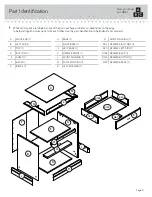
CABINET RIGHT - 1

40AX

CABINET LEFT - 1

40AY

DRAWER RIGHT - 1

40AZ

DRAWER LEFT - 1

Summary of Contents for Barrister Home 5418705

Page 1: ...UCTION BOOKLET CONTAINS IMPORTANT SAFETY INFORMATION PLEASE READ AND KEEP FOR FUTURE REFERENCE Barrister Home Night Stand Barrister Home Collection Model 5418705 Sweet stand Sweet dreams Teknik www teknikoffice co uk ...

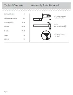
Page 2: ...Required 3 4 5 6 23 24 26 27 29 30 31 Part Identification Hardware Identification Assembly Steps Français Español Safety Warranty Hammer Not actual size No 2 Phillips Screwdriver Tip Shown Actual Size Skip the power trip This time Page 2 ...

Page 3: ...dentify similar parts A RIGHT END 1 B LEFT END 1 C TOP 1 D BOTTOM 1 E SHELF 1 F BACK 1 G BRACE 1 H BASE 1 I RIGHT BASE 1 J LEFT BASE 1 K DRAWER FRONT 1 L FRONT MOLDING 1 M RIGHT MOLDING 1 N LEFT MOLDING 1 O SHELF MOLDING 1 D24 DRAWER RIGHT SIDE 1 D25 DRAWER LEFT SIDE 1 D163 DRAWER BACK 1 D723 DRAWER BOTTOM 1 M67 DRAWER BRACE 1 Now you know our ABCs Page 3 A B C D E F G H I J K L M N O D24 M67 D25 ...

Page 4: ...it U EXTENSION SLIDE 2 T EXTENSION RAIL 2 EXTENSION SET SHOWN SEPARATED METAL BRACKET 5 4G METAL PIN 2 1R MOLDING CONNECTOR 2 19F 10A SLIDE CAM 2 NAIL 24 1N HIDDEN CAM 13 1F CAM DOWEL 13 2F PULL 1 70K KNOB 1 71K Page 4 40AW CABINET RIGHT 1 40AX CABINET LEFT 1 40AY DRAWER RIGHT 1 40AZ DRAWER LEFT 1 ...

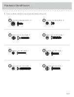
Page 5: ...re with your unit Page 5 SILVER 3 4 MACHINE SCREW 1 20S BLACK 9 16 LARGE HEAD SCREW 10 1S SILVER 1 1 8 FLAT HEAD SCREW 7 10S BLACK 1 1 4 FLAT HEAD SCREW 4 7S BLACK 7 8 MACHINE SCREW 2 37S 18S BROWN 1 FLAT HEAD SCREW 4 3S GOLD 5 16 FLAT HEAD SCREW 12 30S BLACK 1 9 16 FLAT HEAD SCREW 5 ...

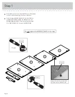
Page 6: ...h thirteen HIDDEN CAMS 1F into the ENDS A and B BOTTOM D SHELF E BRACE G and DRAWER BRACE M67 Then insert the metal end of a CAM DOWEL 2F into each HIDDEN CAM Page 6 Arrow 1F 2F 13 used Arrow 1F 2F Do not tighten the HIDDEN CAMS in this step Insert the metal end of the CAM DOWEL into the HIDDEN CAM Arrow A B E G M67 D ...

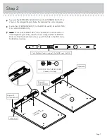
Page 7: ... a SCREW into the hole shown in the enlarged diagram Then slide the inner cartridge of the EXTENSION RAIL in to find the other hole that lines up with the hole in the END Turn a SCREW into this hole Page 7 Open end Open end GOLD 5 16 FLAT HEAD SCREW 4 used in this step 3S Push the black lever in and pull the SLIDE from the RAIL A S u r f a c e w i t h H I D D E N C A M S B S u r f a c e w i t h H I...

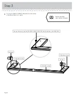
Page 8: ...o the notches in the MOLDINGS L M and N Use your hammer to tap the MOLDING CONNECTORS 19F into the notches in the MOLDINGS Flat end Flat end 19F M N L 19F Unfinished surface Unfinished surface Unfinished surface Page 8 Some assembly and snacks required ...

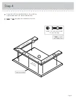
Page 9: ...S 10S å NOTE Do not overtighten the SCREWS into the TOP Page 9 C L N M F i n i s h e d s u r f a c e F i n i s h e d s u r f a c e S u r f a c e w i t h h o l e s F i n i s h e d s u r f a c e SILVER 1 1 8 FLAT HEAD SCREW 7 used in this step 10S Do not overtighten the SCREWS 10S Long curved edge ...

Page 10: ...fastened The unit may collapse Caution Start Tighten Arrow Minimum 190 degrees Caution Risk of damage or injury HIDDEN CAMS must be completely tightened HIDDEN CAMS that are not completely tightened may loosen and parts may separate To completely tighten Arrow Maximum 210 degrees B D Surface with HIDDEN CAMS These holes must be here This hole must be here ...

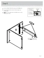
Page 11: ... BRACE G å Fasten the BRACE G to the LEFT END B Tighten one HIDDEN CAM å NOTE Be sure the METAL PIN in the BRACE inserts into the hole in the LEFT END Page 11 G Surface with HIDDEN CAMS 1R Arrow Minimum 190 degrees Maximum 210 degrees Edge without HIDDEN CAM B ...

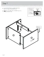
Page 12: ...TTOM D and BRACE G Tighten three HIDDEN CAMS å NOTE Be sure the METAL PIN in the BRACE inserts into the hole in the RIGHT END Step 7 Page 12 Arrow Minimum 190 degrees Maximum 210 degrees Surface without HIDDEN CAMS A D G Edge with CAM DOWELS ...

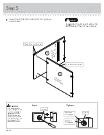
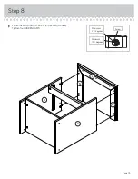
Page 13: ...Step Step 8 å Fasten the MOLDINGS M and N to the ENDS A and B Tighten four HIDDEN CAMS Page 13 Arrow Minimum 190 degrees Maximum 210 degrees A B L M N ...

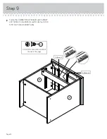
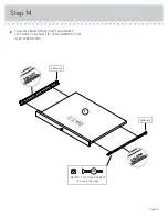
Page 14: ... the CABINET RIGHT 40AW and CABINET LEFT 40AX to the ENDS A and B Use four GOLD 5 16 FLAT HEAD SCREWS 3S Step 9 Page 14 GOLD 5 16 FLAT HEAD SCREW 4 used in this step 3S A B 40AX 40AX Roller end Roller end 40AW 40AW ...

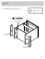
Page 15: ...en the BASES I and J to the ENDS A and B Use four BLACK 1 1 4 FLAT HEAD SCREWS 7S Page 15 B A I J BLACK 1 1 4 FLAT HEAD SCREW 4 used in this step 7S Flat edge Flat edge Don t worry It isn t Rome This can be built in a day ...

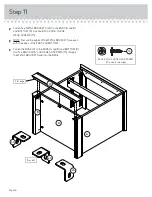
Page 16: ...ure the edges of the METAL BRACKETS are even with the edges of the ENDS and BOTTOM å Fasten the BASE H to the ENDS A and B and BOTTOM D Use five BLACK 9 16 LARGE HEAD SCREWS 1S through the METAL BRACKETS and into the BASE Step 11 Page 16 BLACK 9 16 LARGE HEAD SCREW 10 used in this step 1S 5 used 4G 4G 4G H Flat edge B A D ...

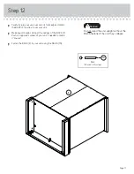
Page 17: ...over your unit å Make equal margins along all four edges of the BACK F Push on opposite corners of your unit if needed to make it square å Fasten the BACK F to your unit using the NAILS 1N Do not stand the unit upright without the BACK fastened The unit may collapse Caution NAIL 24 used in this step 1N F ...

Page 18: ...Fasten the SHELF E to the SHELF MOLDING O Tighten two HIDDEN CAMS Step 13 Page 18 Arrow Minimum 190 degrees Maximum 210 degrees S u r f a c e w i t h H I D D E N C A M S 71K SILVER 3 4 MACHINE SCREW 1 used for the KNOB 20S These holes are closer to this edge O E O Surface with more holes ...

Page 19: ... RIGHT 40AY and DRAWER LEFT 40AZ to the SHELF E Use four BROWN 1 FLAT HEAD SCREWS 18S Page 19 S u r f a c e w i t h o u t H I D D E N C A M S E BROWN 1 FLAT HEAD SCREW 4 used in this step 18S Roller end Roller end 40AZ 40AZ 40AY 40AY ...

Page 20: ...EAD SCREWS 30S Surface with HIDDEN CAM 1 2 3 4 Be sure the DRAWER BOTTOM inserts into the DRAWER FRONT groove With the palm of your hand tap the DRAWER BOTTOM down into the groove Groove Arrow Maximum 210 degrees Minimum 190 degrees K K K D25 D24 D25 D723 D24 D24 D25 D163 Unfinished surface Be sure the DRAWER BOTTOM inserts into the DRAWER BACK groove 30S Start each screw a few turns before complet...

Page 21: ...d 3 å NOTE The screw head in the CAM must be visible through the slotted hole in the SLIDE å Fasten the PULL 70K to the DRAWER FRONT K Use two BLACK 7 8 MACHINE SCREWS 37S Screw head turn CAM to line up holes in the SLIDES with holes in DRAWER SIDES 10A 10A K D24 D25 BLACK 7 8 MACHINE SCREW 2 used for the PULL 37S Open end GOLD 5 16 FLAT HEAD SCREW 4 used in this step 3S 1 2 3 1 2 3 U U Open end 7...

Page 22: ...up and slide it into the unit å To insert the drawer into your unit line up the EXTENSION SLIDES on the drawer with the EXTENSION RAILS on the unit and push the drawer into the unit until the drawer is fully inserted The drawer will push in hard until it is all the way in then it will slide in and out easier Step 17 Page 22 Pro Tip Lift with your legs And you know your arms 40 lbs 10 lbs 20 lbs 30...

Page 23: ... SCREWS when finished with adjustments å NOTE Please read the back pages of the instruction booklet for important safety information å This completes assembly Clean with your favorite furniture polish or a damp cloth Wipe dry Loosen screw 3 a 1 4 turn turn the cam a 1 4 turn maximum in both the clockwise and counter clockwise directions to make adjustments and then tighten screw 3 The higher the sc...

Page 24: ...erloaded drawers or shelves can break Never exceed the weight limits shown in the instructions Work from bottom to top when loading shelves and drawers Place the heavier items on the lower shelves or in lower drawers Placing TVs on furniture items that are not designed to support a television is hazardous Risk of injury or death TVs can be very heavy Plus the weight and location of the picture tub...

Reviews: