background image

Step 23

 å

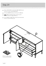
Apply the WARNING LABEL (24) to the TOP (C). You should be able to read the label when the TV is removed
from the unit. When the TV is in place, it should hide the label. Peel off  the backing and apply the label as shown 
in the diagram.

 å

NOTE: This is a permanent label intended to last for the life of the product. Once applied, do not try to remove it.

5

22,68

22,68

70 lbs.

31,75 kg

31,75 kg

5

22

,6

8

22

,6

8

70 lbs.

31,75 kg

31,75 kg

24

C

Page 27

Summary of Contents for Boulevard Cafe 5420667

Page 1: ... for all things awesome Credenza Boulevard Cafe Collection Model 5420667 NOTE THIS INSTRUCTION BOOKLET CONTAINS IMPORTANT SAFETY INFORMATION PLEASE READ AND KEEP FOR FUTURE REFERENCE Teknik www teknikoffice co uk ...

Page 2: ...he diagram below before you begin assembly This Sauder unit is designed for use with televisions weighing less than 70 pounds Never use with a TV that weighs more The size of the television front to back and side to side must fit within the space defined in the diagram Never place the front edge of the TV past the front edge of the TV support shelf or stop molding if equipped Never allow the sides o...

Page 3: ...to help identify similar parts Now you know our ABCs A RIGHT END 1 B LEFT END 1 C TOP 1 D BACK 1 E UPRIGHT 1 F ADJUSTABLE SHELF 2 G DOOR RAIL 2 H SHELF 1 I BOTTOM 1 J REAR LEG 1 K FRONT LEG 1 L LEFT DOOR 1 M RIGHT DOOR 1 N FLIP UP DOOR 1 O LEFT DRAWER SIDE 1 P DRAWER BACK 1 Q DRAWER BOTTOM 1 R RIGHT DRAWER SIDE 1 S DRAWER BRACE 1 T DRAWER FRONT 1 A B C D E F F G G H I J K L M N O P Q R S T Page 3 ...

Page 4: ...FLAT HEAD SCREW 16 18 BLACK 1 FLAT HEAD SCREW 6 19 BLACK 1 1 2 ALLEN HEAD SCREW 6 17 ANGLED HEAD CAM SCREW 18 5 Angled head HINGE 4 13 HINGE BRACKET 4 12 METAL PIN 8 8 DOOR STOP 2 10 PULL 1 16 EXTENSION SET SHOWN SEPARATED DOOR PULL 2 15 GROMMET WITH CAP 2 11 STRAIGHT HEAD CAM SCREW 6 6 Straight head THREADED PIN 2 9 1 EXTENSION RAIL 2 2 EXTENSION SLIDE 2 Refer to the step 23 for proper location a...

Page 5: ...arton to avoid scratching your unit or the floor å Push eighteen LARGE HIDDEN CAMS 3 into the ENDS A and B BACK D UPRIGHT E and SHELF H Arrow 18 used Arrow Arrow 3 3 The arrow in the HIDDEN CAM must point toward the hole in the edge of the board Hole A B D E H Page 5 ...

Page 6: ...Step 2 å Fasten the HINGE BRACKETS 12 to the LEFT END B and UPRIGHT E Use the screws in the HINGE BRACKETS å NOTE Be sure to use the exact holes shown B E 12 Page 6 12 ...

Page 7: ...Step 3 å Turn eighteen ANGLED HEAD CAM SCREWS 5 into the ENDS A and B TOP C and UPRIGHT E Angled head 5 18 used C A B E Page 7 ...

Page 8: ... E Use six BLACK 1 FLAT HEAD SCREWS 19 å Fasten the DOOR STOPS 10 to the RIGHT END A and UPRIGHT E Use four BLACK 1 2 PAN HEAD SCREWS 23 10 10 BLACK 1 FLAT HEAD SCREW 6 used for the DOOR RAILS 19 A E BLACK 1 2 PAN HEAD SCREW 4 used for the DOOR STOPS 23 G G Page 8 ...

Page 9: ...rged diagram Then slide the inner cartridge of the EXTENSION RAIL in to find the other holes that lines up with the holes in the END and UPRIGHT Turn a SCREW into these holes å NOTE The EXTENSION SLIDES will be used later for the DRAWERS Use these holes to fasten the EXTENSION RAIL to the END and UPRIGHT Push the black lever down and pull the SLIDE from the RAIL 1 1 1 2 BLACK 1 2 PAN HEAD SCREW 6 u...

Page 10: ...D DOWELS 7 into the BACK D å Fasten the UPRIGHT E to the BACK D by placing the back edge of the UPRIGHT over the WOOD DOWELS 7 Step 6 D E 7 S u r f a c e w i t h H I D D E N C A M S The DOOR RAIL G should be here Page 10 ...

Page 11: ...HT E å Fasten the SHELF H to the UPRIGHT E Tighten two HIDDEN CAMS å NOTE Be sure the WOOD DOWELS in the UPRIGHT insert into the holes in the SHELF Step 7 Surface with HIDDEN CAMS The HIDDEN CAMS should be closer to this edge H E 7 Page 11 1 2 ...

Page 12: ...sure the WOOD DOWELS in the LEFT END insert into the BACK D å Insert four WOOD DOWELS 7 into the RIGHT END A å Fasten the RIGHT END A to the BACK D and SHELF H Tighten four HIDDEN CAMS å NOTE Be sure the WOOD DOWELS in the RIGHT END insert into the BACK and SHELF Surface with holes Surface without holes 7 7 B A D H Page 12 1 2 ...

Page 13: ...Fasten the BOTTOM I to the ENDS A and B BACK D and UPRIGHT E Use ten BLACK 1 1 2 FLAT HEAD SCREWS 18 å NOTE Be sure the WOOD DOWELS in the ENDS BACK and UPRIGHT insert into the holes in the BOTTOM 7 7 B A Surface with less holes I BLACK 1 1 2 FLAT HEAD SCREW 10 used in this step 18 E Page 13 D ...

Page 14: ...ther person carefully stand your unit upright å Insert nine WOOD DOWELS 7 into the TOP C å Fasten the TOP C to the ENDS A and B BACK D and UPRIGHT E Tighten eight HIDDEN CAMS A B C D E 7 Page 14 1 2 Caution Two person lift required ...

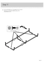
Page 15: ...Step 11 å Fasten the REAR LEG J to the FRONT LEG K Use three BLACK 1 2 ALLEN HEAD SCREWS 20 and the ALLEN WRENCH 25 J K BLACK 1 2 ALLEN HEAD SCREW 3 used in this step 20 Page 15 25 ...

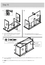
Page 16: ...refully flip your unit onto its TOP C å Fasten the LEGS J and K to the BOTTOM I Use six BLACK 1 1 2 ALLEN HEAD SCREWS 17 and the ALLEN WRENCH 25 BLACK 1 2 ALLEN HEAD SCREW 6 used in this step 17 J K I Page 16 C Caution Two person lift required 25 ...

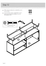
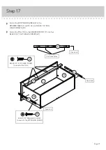
Page 17: ...wn below å 2 Place the FLIP UP DOOR N over the THREADED PIN 9 in the RIGHT END A å 3 While holding the FLIP UP DOOR horizontal turn the remaining THREADED PIN 9 through the slotted hole in the FILIP UP DOOR N and into the hole in the UPRIGHT E Step 13 1st 2nd 3rd E Page 17 A Side Step Make nachos Optional but recommended D N 9 9 ...

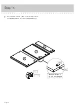
Page 18: ...MALL HIDDEN CAMS 4 into the large holes in the DRAWER SIDES O and R and DRAWER BRACE S Step 14 4 Arrow 6 used Arrow The arrow in the HIDDEN CAM must point toward the hole in the edge of the board Hole O R S Page 18 ...

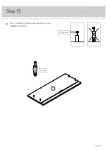
Page 19: ...å Turn six STRAIGHT HEAD CAM SCREWS 6 into the DRAWER FRONT T Step 15 Straight head 6 6 used T Page 19 ...

Page 20: ...WER FRONT T Tighten six SMALL HIDDEN CAMS å Slide a DRAWER BOTTOM Q into the grooves in the DRAWER SIDES O and R and DRAWER FRONT T Groove Be sure the DRAWER BOTTOM inserts into the DRAWER BACK groove BLACK 1 1 2 FLAT HEAD SCREW 6 used in this step 18 P 1 2 3 R R R O O O S S T T T Q Q Unfinished surface å NOTE Be sure the DRAWER BOTTOM Q inserts into the groove of the DRAWER BACK P Page 20 ...

Page 21: ...K 1 2 PAN HEAD SCREWS 23 å Fasten the PULL 16 to the DRAWER FRONT T Use four BLACK 1 2 FLAT HEAD SCREWS 22 Open end Open end BLACK 1 2 PAN HEAD SCREW 6 used for the EXTENSION SLIDES 23 Use these holes Open end 16 T O R 2 2 2 BLACK 1 2 FLAT HEAD SCREW 4 used for the PULL 22 Page 21 ...

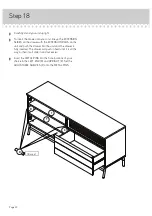
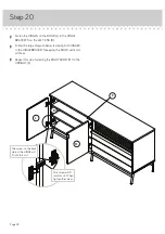
Page 22: ...the unit and push the drawer into the unit until the drawer is fully inserted The drawer will push in hard until it is all the way in then it will slide in and out easier å Insert the METAL PINS into the hole locations of your choice in the LEFT END B and UPRIGHT E Set the ADJUSTABLE SHELVES F onto the METAL PINS Step 18 8 F F Page 22 B E 8 used ...

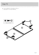
Page 23: ...å Fasten the HINGES 13 to the DOORS L and M Use eight SILVER 1 2 FLAT HEAD SCREWS 21 Step 19 13 13 M L Page 23 SILVER 1 2 FLAT HEAD SCREW 8 used in this step 21 ...

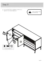
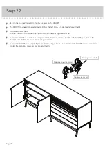
Page 24: ...rge diagram below fastening both HINGES to the HINGE BRACKETS keeping the DOOR vertical at all times å Repeat this step fastening the RIGHT DOOR M to the UPRIGHT E This screw will fit into this slot Then tighten the screw The screw on the back side of the HINGE will fit into this slot Page 24 B L E M ...

Page 25: ...å Fasten the PULLS 15 to the DOORS L and M Use four BLACK 1 2 FLAT HEAD SCREWS 22 Step 21 BLACK 1 2 FLAT HEAD SCREW 4 used for the PULLS 22 Page 25 15 15 L M Hey It s starting to look like something ...

Page 26: ...adjusting screw in or out å To adjust the DOORS up and down vertical loosen both vertical adjustment screws Move the DOORS up or down to the desired location Tighten the screws after making adjustments å To adjust the DOORS in or out depth loosen the mounting screw one turn and move the DOORS in or out as needed Tighten the mounting screw after making adjustments Adjusting screw horizontal Mountin...

Page 27: ...it When the TV is in place it should hide the label Peel off the backing and apply the label as shown in the diagram å NOTE This is a permanent label intended to last for the life of the product Once applied do not try to remove it 5 22 68 22 68 70 lbs 31 75 kg 31 75 kg 5 22 68 22 68 70 lbs 31 75 kg 31 75 kg 24 C Page 27 ...

Page 28: ...he holes in the BACK D å NOTE Please read the back pages of the instruction booklet for important safety information å This completes assembly Clean with your favorite furniture polish or a damp cloth Wipe dry 70 lbs 35 lbs 25 lbs 25 lbs 50 lbs 35 lbs Page 28 To cover HIDDEN CAMS 11 14 D 5 22 68 22 68 70 lbs 31 75 kg 31 75 kg ...

Page 29: ... and or video equipment may result in death or serious injury due to furniture collapse or over turning onto a child NEVER place a TV on furniture that is not intended to support a TV NEVER exceed the maximum size and weight of the TV shown in the instructions Be sure to apply the TV warning label as shown in the instructions Overloading drawers and shelves may result in furniture that can break o...

Reviews: