background image

 å

Fasten two EXTENSION SLIDES (2) to the DRAWER

SIDES (H and P). Use six 3/8" FLAT HEAD SCREWS (22) 

in the exact holes shown.

 å

Fasten one PULL (12) to the DRAWER FRONT (F). Use two

1/2" MACHINE SCREWS (20).

 å

Repeat this step for the other drawer.

Step 11

Page 17

2

Open end

2

2

F

12

H

P

3/8" FLAT HEAD SCREW 

(12 used for the SLIDES)

22

Open end

Open end

1/2" MACHINE SCREW 

(4 used for the PULLS)

20

Summary of Contents for Boulevard Cafe 5427345

Page 1: ... INSTRUCTION BOOKLET CONTAINS IMPORTANT SAFETY INFORMATION PLEASE READ AND KEEP FOR FUTURE REFERENCE Lateral File Boulevard Cafe Collection Model 5427345 Get all organized and stuff Teknik www teknikoffice co uk ...

Page 2: ...ification Hardware Identification Hardware Usage Guide Assembly Steps Safety No 2 Phillips Screwdriver Tip Shown Actual Size Table of Contents Assembly Tools Required Hammer Not actual size 3 4 5 6 7 22 23 Page 2 ...

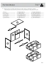
Page 3: ...part identification to help identify similar parts Now you know our ABCs A TOP 1 B LEFT END 1 C RIGHT END 1 D LEFT BACK 1 E RIGHT BACK 1 F DRAWER FRONT 2 G DRAWER BACK 2 H LEFT DRAWER SIDE 2 J DRAWER BOTTOM 2 K DRAWER BRACE 2 L LOWER FRONT BRACE 1 M UPPER FRONT BRACE 1 N LOWER BACK BRACE 1 P RIGHT DRAWER SIDE 2 Q UPPER BACK BRACE 1 Page 3 A B C D E F G H J K L M N P Q F G H J K P ...

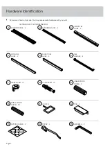
Page 4: ...unit Page 4 EXTENSION SET SHOWN SEPARATED 1 EXTENSION RAIL 4 2 EXTENSION SLIDE 4 3 FRONT FILE GLIDE 2 4 LONG FILE GLIDE 2 5 SHORT FILE GLIDE 4 6 FILE HANGER 4 CAM SCREW 10 8 LARGE WOOD DOWEL 2 9 SMALL WOOD DOWEL 18 10 HOOK 2 11 PULL 2 12 L WRENCH 2 15 APPLIQUE CARD 2 13 STRAP 2 14 HIDDEN CAM 10 7 ...

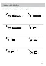
Page 5: ...al size You may receive extra hardware with your unit Page 5 9 16 PAN HEAD SCREW 18 19 1 3 4 HEX HEAD SCREW 4 16 1 1 2 FLAT HEAD SCREW 12 17 1 2 MACHINE SCREW 4 20 3 8 FLAT HEAD SCREW 24 22 1 1 2 HEX HEAD SCREW 8 18 3 8 HEX HEAD SCREW 4 21 NUT 4 23 ...

Page 6: ...r gently tap the CAM DOWEL until the shoulder is against the surface of the part 1 Hidden Cam Hidden Cam Arrow Push a HIDDEN CAM into the part The arrow in the HIDDEN CAM must point toward the hole in the edge of the board Hole 2 3 1 2 Insert the CAM SCREW or CAM DOWEL into the HIDDEN CAM Tighten the HIDDEN CAM Hardware Usage Guide Page 6 ...

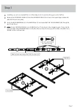
Page 7: ...S B and C Use twelve 3 8 FLAT HEAD SCREWS 22 through the exact holes shown å NOTE For each EXTENSION RAIL turn a SCREW into the 1st hole shown in the enlarged diagram Then slide the inner cartridge of the EXTENSION RAIL in to find the other two holes that line up with the holes in the END Turn a SCREW into each of these holes Page 7 B C Slide the black lever and pull the SLIDE from the RAIL 1 2 1s...

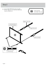
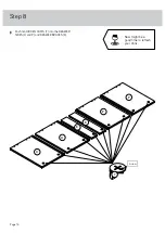
Page 8: ...en two 1 1 2 HEX HEAD SCREWS 18 using the L WRENCH 15 Step 2 Page 8 15 B N Q The EXTENSION RAILS are closer to this edge 1 1 2 HEX HEAD SCREW 2 used in this step 18 Edge with three tabs Edge with four tabs Surface with holes Some assembly and snacks required ...

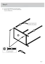
Page 9: ...FRONT BRACES L and M to the LEFT END B Tighten two 1 1 2 HEX HEAD SCREWS 18 using the L WRENCH 15 Step 3 Page 9 15 1 1 2 HEX HEAD SCREW 2 used in this step 18 B L M The tabs face down and are closer to this surface ...

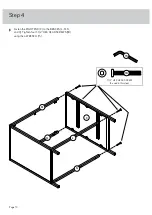
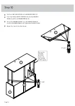
Page 10: ...å Fasten the RIGHT END C to the BRACES L M N and Q Tighten four 1 1 2 HEX HEAD SCREWS 18 using the L WRENCH 15 Step 4 Page 10 15 N Q L M C 1 1 2 HEX HEAD SCREW 4 used in this step 18 ...

Page 11: ...DOWELS 9 into the holes in the BACKS D and E as shown å Turn the HOOKS 11 into the BACKS D and E until they are snug å NOTE The open side of the HOOK should face the short edge of the BACK Step 5 Page 11 E D 9 11 Surface with holes Surface with holes Edge with holes ...

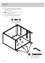
Page 12: ...NCH 15 å NOTE You should start each SCREW a few turns before completely tightening any of them å Fasten the UPPER BACK BRACE Q to the BACKS D and E Use four 9 16 PAN HEAD SCREWS 19 Step 6 Page 12 N E D 15 9 16 PAN HEAD SCREW 4 used for the UPPER BRACE 19 Q 1 3 4 HEX HEAD SCREW 4 used for the LOWER BRACE 16 ...

Page 13: ...e UPPER BRACES M and Q Use six 9 16 PAN HEAD SCREWS 19 å NOTE You should start each SCREW a few turns before completely tightening any of them Step 7 Page 13 Q A Surface with holes M 9 16 PAN HEAD SCREW 6 used in this step 19 ...

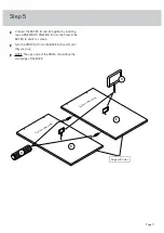
Page 14: ...å Push ten HIDDEN CAMS 7 into the DRAWER SIDES H and P and DRAWER BRACES K Step 8 Page 14 P K H 7 Arrow P K H Now might be a good time to refresh your drink ...

Page 15: ...CE K to the DRAWER BACK G Use two 1 1 2 FLAT HEAD SCREWS 17 å Slide the DRAWER BOTTOM J into the grooves in the DRAWER SIDES H and P and DRAWER BACK G å Repeat this step for the other drawer Step 9 Page 15 J G K P H G Groove Be sure the DRAWER BOTTOM inserts into the DRAWER BACK groove 10 10 8 used 1 1 2 FLAT HEAD SCREW 12 used in this step 17 Surface with HIDDEN CAM P H ...

Page 16: ...he DRAWER SIDES H and P and DRAWER BRACE K å Fasten the DRAWER FRONT F to the DRAWER SIDES H and P and DRAWER BRACE K Tighten five HIDDEN CAMS å Repeat this step for the other drawer Step 10 Page 16 8 F 10 used Be sure the DRAWER BOTTOM inserts into the DRAWER FRONT groove F K P H 10 10 used ...

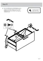
Page 17: ...S 22 in the exact holes shown å Fasten one PULL 12 to the DRAWER FRONT F Use two 1 2 MACHINE SCREWS 20 å Repeat this step for the other drawer Step 11 Page 17 2 Open end 2 2 F 12 H P 3 8 FLAT HEAD SCREW 12 used for the SLIDES 22 Open end Open end 1 2 MACHINE SCREW 4 used for the PULLS 20 ...

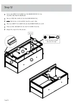
Page 18: ...e DRAWER BACK G å NOTE The file tabs on the GLIDES should face each other å Press two SHORT FILE GLIDES 5 onto the DRAWER SIDES H and P å Place two FILE HANGERS 6 onto the FILE GLIDES 3 and 4 å Repeat this step for the other drawer Step 12 Page 18 9 16 PAN HEAD SCREW 8 used in this step 19 3 4 H F P G 5 5 3 4 6 6 File tab ...

Page 19: ...ER tighten two 3 8 HEX HEAD SCREWS 21 through the STRAPS 14 through the DRAWER BACK G and into the NUTS 23 using both L WRENCHES 15 Step 13 Page 19 G 14 14 3 8 HEX HEAD SCREW 2 used in this step 21 15 15 23 If you re doing this to help a friend don t leave without a bite ...

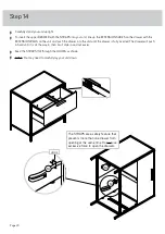
Page 20: ...unit until the drawer is fully inserted The drawer will push in hard until it is all the way in then it will slide in and out easier å Feed the STRAPS 14 through the HOOKS as shown å NOTE You may need to carefully lay your unit down Step 14 Page 20 14 14 14 HOOK The STRAPS are a safety feature that prevents more than one drawer from opening at the same time Do not use excessive force to open the d...

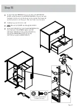
Page 21: ... it is all the way in then it will slide in and out easier å Carefully lay your unit onto its side å NOTE Be sure the STRAPS are through the HOOKS å Fasten both STRAPS 14 to the lower DRAWER BACK G From the back of the DRAWER tighten two 3 8 HEX HEAD SCREWS 21 through the STRAPS 14 through the DRAWER BACK G and into the NUTS 23 using both L WRENCHES 15 Step 15 Page 21 15 G 14 14 23 15 3 8 HEX HEAD...

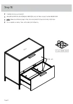
Page 22: ...QUE CARDS 13 and stick them onto each visible HIDDEN CAM å NOTE Please read the back pages of the instruction booklet for important safety information å This completes assembly Clean with a damp cloth Wipe dry Step 16 Page 22 13 To cover HIDDEN CAMS 35 lbs 35 lbs each ...

Page 23: ... heavier items in the lower drawer Improperly moving furniture Furniture can tip over or break if improperly moved Physical injury Furniture can be very heavy Unload drawers from top to bottom before moving the lateral file Do not push furniture especially on a carpeted floor Have a friend help you lift the item and set it in place Placing TVs on furniture items that are not designed to support a ...

Reviews: