background image

Step 

Page 17

Step 13

Unfi

 nished 

sur

face

 å

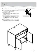
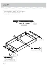
Fasten the DRAWER BACK (L) to the DRAWER SIDES (K and M) and DRAWER BRACE (O). Use six BLACK 1-1/2" FLAT
HEAD SCREWS (17).

 å

NOTE: Be sure the DRAWER BOTTOM (N) inserts into the groove of the DRAWER BACK (L).

1

2

3

 å

Fasten the  DRAWER SIDES (K and M) and DRAWER
BRACE (O) to the DRAWER FRONT (P). Tighten six 
HIDDEN CAMS

 å

Slide the DRAWER BOTTOM (N) into the grooves in the
DRAWER SIDES (K and M) and DRAWER FRONT (P). 

Groove

Be sure the 
DRAWER 
BOTTOM inserts 
into the DRAWER 
BACK groove.

1

2

BLACK 1-1/2" FLAT HEAD SCREW

(6 used in this step)

17

K

K

K

L

M

M

M

N

N

O

O

P

P

Surface with HIDDEN CAMS

Summary of Contents for Clifton Place 5421115

Page 1: ...office co uk The stories of your life Storage Sideboard Clifton Place Collection Model 5421115 NOTE THIS INSTRUCTION BOOKLET CONTAINS IMPORTANT SAFETY INFORMATION PLEASE READ AND KEEP FOR FUTURE REFERENCE Teknik ...

Page 2: ...mbly Tools Required Part Identification Hardware Identification Assembly Steps Français Español Safety Warranty No 2 Phillips Screwdriver Tip Shown Actual Size Skip the power trip This time 3 4 5 21 22 25 26 28 29 30 31 Page 2 ...

Page 3: ...n to help identify similar parts Now you know our ABCs A RIGHT END 1 B LEFT END 1 C TOP 1 D TOP MOLDING 1 E UPPER BACK 1 F BRACE 1 G ADJUSTABLE SHELF 1 H LOWER BACK 1 I BOTTOM 1 J BOTTOM MOLDING 2 K LEFT DRAWER SIDE 1 L DRAWER BACK 1 M RIGHT DRAWER SIDE 1 N DRAWER BOTTOM 1 O DRAWER BRACE 1 P DRAWER FRONT 1 Q LEFT DOOR 1 R RIGHT DOOR 1 S FOOT 4 A B C D E F G H I J J K L M N O S S S S P Q R Page 3 ...

Page 4: ...L PIN 4 15 RUBBER SLEEVE 4 16 APPLIQUE CARD 1 13 BLACK 1 1 2 FLAT HEAD SCREW 8 17 SILVER 1 2 FLAT HEAD SCREW 14 19 BLACK 1 2 PAN HEAD SCREW 12 20 SMALL HIDDEN CAM 6 3 STRAIGHT HEAD CAM SCREW 6 4 Straight head LARGE APPLIQUE CARD 1 14 ADJUSTABLE GLIDE 4 10 HINGE BRACKET 4 11 HINGE 4 12 GROMMET WITH CAP 1 9 PULL 3 8 BLACK 1 1 8 FLAT HEAD SCREW 9 18 EXTENSION SET SHOWN SEPARATED T EXTENSION RAIL 2 U ...

Page 5: ... NOTE If you are attaching the 421116 Hutch to your unit build the Hutch first å Push twenty LARGE HIDDEN CAMS 1 into the ENDS A and B BRACE F LOWER BACK H UPPER BACK E and BOTTOM I Arrow 20 used Arrow Arrow 1 1 The arrow in the HIDDEN CAM must point toward the hole in the edge of the board Hole A B F E I H Page 5 ...

Page 6: ...ch large hole in the BOTTOM I å Flip the BOTTOM I over å Turn and tighten four FEET S into the threaded holes in the BOTTOM I å Turn four ADJUSTABLE GLIDES 10 into the threaded holes in the FEET S I I S S S S 10 Flip the B O T T O M o v e r Page 6 Surface without HIDDEN CAMS 14 ...

Page 7: ...o the BOTTOM I å Fasten the BOTTOM MOLDINGS J to the BOTTOM I Use six BLACK 1 1 8 FLAT HEAD SCREWS 18 å NOTE Be sure the SHORT WOODEN DOWELS insert into the holes in the BOTTOM MOLDINGS 7 7 J J I BLACK 1 1 8 FLAT HEAD SCREW 6 used in this step 18 Page 7 ...

Page 8: ...Step Step 4 2 20 used Angled head Remember Righty tighty Lefty loosey å Turn twenty ANGLED HEAD CAM SCREWS 2 into the ENDS A and B and TOP C A B C Page 8 ...

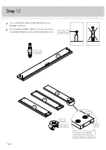
Page 9: ...reasy å Fasten two EXTENSION RAILS T to the ENDS A and B Use six BLACK 1 2 PAN HEAD SCREWS 20 å NOTE For each EXTENSION RAIL turn a SCREW into the hole shown in the enlarged diagram Then slide the inner cartridge of the EXTENSION RAIL in to find the other holes that line up with the holes in the ENDS Turn a SCREW into those holes å NOTE The EXTENSION SLIDES will be used later for the DRAWERS å Fast...

Page 10: ...rt four LONG WOOD DOWELS 5 into the LOWER BACK H å Fasten the UPPER BACK E to the LOWER BACK H by pushing it onto the WOOD DOWELS in the LOWER BACK 5 5 Surface with HIDDEN CAMS Surface with HIDDEN CAMS E H Page 10 Notch ...
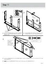
Page 11: ...RIGHT END insert into the holes in the BACKS å Fasten the BRACE F to the RIGHT END A Tighten the HIDDEN CAM å NOTE Be sure the WOOD DOWEL in the RIGHT END inserts into the hole in the BRACE å Insert two WOOD DOWELS 6 into the long edge of the LOWER BACK H E F H Surface with HIDDEN CAMS Surface with HIDDEN CAMS 1 2 A 6 6 Surface with HIDDEN CAMS Rounded edge Notch Page 11 ...
Page 12: ...ND A Tighten two HIDDEN CAMS å NOTE Be sure the WOOD DOWELS in the RIGHT END and LOWER BACK insert into the holes in the BOTTOM å Fasten the BOTTOM I to the LOWER BACK H as shown in the lower diagram Use two BLACK 1 1 2 FLAT HEAD SCREWS 17 1 2 6 BLACK 1 1 2 FLAT HEAD SCREW 2 used in this step 17 A A I I H H Page 12 Rounded edge ...

Page 13: ... Fasten the LEFT END B to the UPPER BACK E BRACE F LOWER BACK H and BOTTOM I Tighten seven HIDDEN CAMS å NOTE Be sure the WOOD DOWELS in the LEFT END insert into the holes in the BACKS BOTTOM and BRACE Step 9 I H B 6 6 Surface without holes 1 2 E F Page 13 ...

Page 14: ... HEAD SCREWS 18 å NOTE Be sure the SHORT WOOD DOWELS in the TOP insert into the holes in the TOP MOLDING BLACK 1 1 8 FLAT HEAD SCREW 3 used in this step 18 7 Rounded edge C D Page 14 Remember Righty tighty Lefty loosey STOP Before you proceed to the next step If you are attaching the 5421116 Hutch to your unit build the Hutch now ...

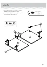
Page 15: ...D DOWELS 6 into the ENDS A and B and UPPER BACK E å Fasten the TOP C to the ENDS A and B and UPPER BACK E Tighten six HIDDEN CAMS å NOTE Be sure the WOOD DOWELS in the ENDS and UPPER BACK insert into the holes in the TOP B C 6 6 This hole must be here A 1 2 E Page 15 ...

Page 16: ...he arrow in the HIDDEN CAM must point toward the hole in the edge of the board Hole å Turn six STRAIGHT HEAD CAM SCREWS 4 into the DRAWER FRONT P å Push six SMALL HIDDEN CAMS 3 into the large holes in the DRAWER SIDES K and M and DRAWER BRACE O P K O M Page 16 ...

Page 17: ...the groove of the DRAWER BACK L 1 2 3 å Fasten the DRAWER SIDES K and M and DRAWER BRACE O to the DRAWER FRONT P Tighten six HIDDEN CAMS å Slide the DRAWER BOTTOM N into the grooves in the DRAWER SIDES K and M and DRAWER FRONT P Groove Be sure the DRAWER BOTTOM inserts into the DRAWER BACK groove 1 2 BLACK 1 1 2 FLAT HEAD SCREW 6 used in this step 17 K K K L M M M N N O O P P Surface with HIDDEN C...

Page 18: ... six BLACK 1 2 PAN HEAD SCREWS 20 å Fasten the PULL 8 to the DRAWER FRONT P Use two SILVER 1 2 FLAT HEAD SCREWS 19 M K P U U Use these holes U BLACK 1 2 PAN HEAD SCREW 6 used for the EXTENSION SLIDES 20 Open end Open end Open end 8 SILVER 1 2 FLAT HEAD SCREW 2 used for the PULL 19 ...

Page 19: ... and R Use eight SILVER 1 2 FLAT HEAD SCREWS 19 å Fasten the PULLS 8 to the DOORS Q and R Use four SILVER 1 2 FLAT HEAD SCREWS 19 SILVER 1 2 FLAT HEAD SCREW 12 used in this step 19 R Q Side Step Make nachos Optional but recommended 12 12 8 Page 19 ...

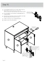
Page 20: ...OR R to the HINGE BRACKETS on the RIGHT END A å Follow the large diagram below fastening both HINGES to the HINGE BRACKETS keeping the DOOR vertical at all times å Tighten the mounting screws in the HINGE BRACKETS å Repeat this step for the LEFT DOOR Q Step 16 This screw will fit into this slot Then tighten the screw The screw on the back side of the HINGE will fit into this slot Mounting screw R A ...

Page 21: ...g screw in or out å To adjust the DOORS up and down vertical loosen both vertical adjustment screws Move the DOORS up or down to the desired location Tighten the screws after making adjustments å To adjust the DOORS in or out depth loosen the mounting screw one turn and move the DOORS in or out as needed Tighten the mounting screw after making adjustments Step 17 Adjusting screw horizontal Mountin...

Page 22: ... The drawer will push in hard until it is all the way in then it will slide in and out easier å NOTE To raise a corner of the unit turn the ADJUSTABLE GLIDE counter clockwise To lower a corner turn the ADJUSTABLE GLIDE clockwise å NOTE Please read the back pages of the instruction booklet for important safety information å This completes assembly Clean with your favorite furniture polish or a damp...

Page 23: ...ters Furniture can tip over or break if improperly moved Physical injury Furniture can be very heavy Unload shelves from top to bottom before moving the furniture Do not push furniture especially on a carpeted floor Have a friend help you lift the item and set it in place This unit must be positioned against a wall Children climbing on the shelves can cause the product to tip Risk of injury or deat...

Reviews: