background image

 å

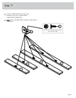
Fasten six METAL BRACKETS (4G) to the

BASES (E and F). Use six BLACK 9/16"  

LARGE HEAD SCREWS (1S).

 å

NOTE: Be sure the BRACKETS are even with the edges of

the BASES.

Step 11

E

E

F

F

4G

BLACK 9/16" LARGE HEAD SCREW

(6 used in this step)

1S

Page 17

Summary of Contents for Elstree 5426908

Page 1: ...Elstree 2 Drawer Lateral Filer Model 5426908 Congratulations You are now an adult Teknik www teknikoffice co uk...

Page 2: ...s Required Part Identification Hardware Identification Assembly Steps Fran ais Espa ol Safety Warranty Hammer Not actual size No 2 Phillips Screwdriver Tip Shown Actual Size 3 4 5 6 29 30 34 35 39 40...

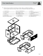
Page 3: ...ication to help identify similar parts Now you know our ABCs A RIGHT END 1 B LEFT END 1 C TOP 1 D BOTTOM 1 D550 RIGHT DRAWER SIDE 2 D551 LEFT DRAWER SIDE 2 D552 DRAWER BACK 2 D985 DRAWER BOTTOM 2 E LA...

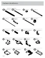
Page 4: ...IDE 4 4B EXTENSION SET SHOWN SEPARATED EXTENSION RAIL 4 35MA EXTENSION SLIDE 4 35MC 10A SLIDE CAM 4 FILE ROD 4 9B FILE BAR 4 14B SMALL FILE BRACKET 2 11B HIDDEN CAM 6 1F METAL BRACKET 6 4G WOOD DOWEL...

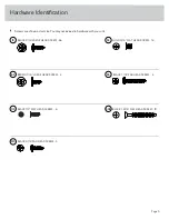
Page 5: ...extra hardware with your unit BLACK 9 16 PAN HEAD SCREW 3 51S BLACK 1 1 8 PAN HEAD SCREW 4 9S BROWN 7 16 LARGE HEAD SCREW 4 6S BLACK 1 2 FLAT HEAD SCREW 6 11S 30S BLACK 1 9 16 FLAT HEAD SCREW 10 BLAC...

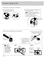
Page 6: ...in the part 1 HOW TO USE A TWIST LOCK FASTENER HOW TO USE A HIDDEN CAM CAM DOWEL 2 Insert the metal end of the CAM DOWEL into the HIDDEN CAM 1 Push a HIDDEN CAM into the part The arrow in the HIDDEN...

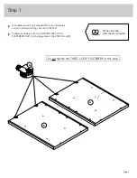
Page 7: ...mpty carton to avoid scratching your unit or the floor To begin assembly push four SAUDER TWIST LOCK FASTENERS 36F into the large holes in the ENDS A and B A B 36F Do not tighten the TWIST LOCK FASTEN...

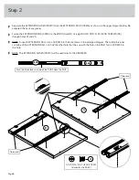
Page 8: ...EXTENSION RAIL turn a SCREW into the hole shown in the enlarged diagram Then slide the inner cartridge of the EXTENSION RAIL in to find the other hole that lines up with the hole in the END Turn a SC...

Page 9: ...A Use three BLACK 9 16 PAN HEAD SCREWS 51S Fasten the L LOCK BRACKET 76G to the RIGHT END A Use two BLACK 9 16 LARGE HEAD SCREWS 1S Step 3 A 34G BLACK 9 16 PAN HEAD SCREW 3 used in this step 51S BLACK...

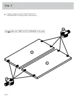
Page 10: ...To begin assembly push eight SAUDER TWIST LOCK FASTENERS 36F into the large holes in the BACKS G Step 4 G G 36F Do not tighten the TWIST LOCK FASTENERS in this step 36F Page 10...

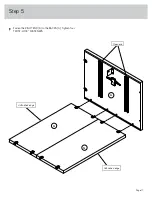
Page 11: ...Fasten the RIGHT END A to the BACKS G Tighten four TWIST LOCK FASTENERS Step 5 A G G Unfinished edge Unfinished edge Open end Page 11...

Page 12: ...our HIDDEN CAMS 1F into the BOTTOM D Then insert the metal end of a CAM DOWEL 2F into each HIDDEN CAM Step 6 D Do not tighten the HIDDEN CAMS in this step 1F 2F Arrow Metal end 1F 2F Metal end Arrow P...

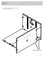
Page 13: ...Fasten the BOTTOM D to the RIGHT END A Tighten two HIDDEN CAMS Step 7 D A These edges must be even Surface with HIDDEN CAMS Page 13...

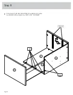
Page 14: ...Fasten the LEFT END B to the BOTTOM D and BACKS G Tighten two HIDDEN CAMS and tighten four TWIST LOCK FASTENERS Step 8 B G G D Open end Page 14 1 2...

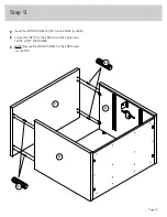
Page 15: ...t four WOOD DOWELS 15F into the ENDS A and B Fasten the TOP C to the ENDS A and B Tighten four TWIST LOCK FASTENERS NOTE Be sure the WOOD DOWELS in the ENDS insert into the TOP Step 9 B A C 15F 15F Pa...

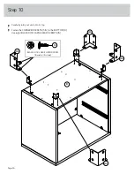
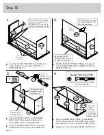
Page 16: ...ully turn your unit onto its top Fasten the CORNER BRACKETS 31G to the BOTTOM D Use eight BLACK 9 16 LARGE HEAD SCREWS 1S Step 10 D 31G 31G 31G 31G BLACK 9 16 LARGE HEAD SCREW 8 used in this step 1S P...

Page 17: ...L BRACKETS 4G to the BASES E and F Use six BLACK 9 16 LARGE HEAD SCREWS 1S NOTE Be sure the BRACKETS are even with the edges of the BASES Step 11 E E F F 4G BLACK 9 16 LARGE HEAD SCREW 6 used in this...

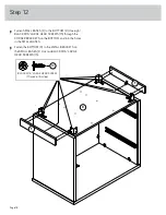
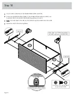
Page 18: ...D SCREWS 1S through the CORNER BRACKETS on the BOTTOM and into the holes in the SMALL BASES Fasten the BOTTOM D to the METAL BRACKETS on the SMALL BASES F Use two BLACK 9 16 LARGE HEAD SCREWS 1S Step...

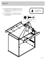
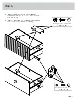
Page 19: ...CORNER BRACKETS on the BOTTOM and into the holes in the LARGE BASES Fasten the BOTTOM D to the METAL BRACKETS on the LARGE BASES E Use four BLACK 9 16 LARGE HEAD SCREWS 1S Step 13 D E E BLACK 9 16 LAR...

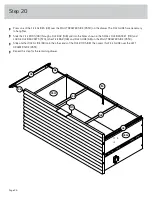
Page 20: ...Fasten the BALLAST J to the BOTTOM D Use four BLACK 1 1 8 PAN HEAD SCREWS 9S Step 14 J D 9S BLACK 1 1 8 PAN HEAD SCREW 4 used in this step Page 20...

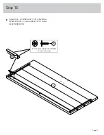
Page 21: ...Fasten the Z LOCK BRACKET 77G to the SMALL DRAWER FRONT K Use two BLACK 9 16 LARGE HEAD SCREWS 1S Step 15 K 77G BLACK 9 16 LARGE HEAD SCREW 2 used in this step 1S Page 21...

Page 22: ...16 FLAT HEAD SCREWS 30S Repeat this step for the LARGE DRAWER FRONT H 1 2 3 4 Be sure the DRAWER BOTTOM inserts into the DRAWER FRONT groove Groove K K K D985 D552 Unfinished surface Be sure the DRAW...

Page 23: ...EAD SCREWS 1S Fasten the SMALL FILE BRACKET 11B to the DRAWER BACK D552 Use two BROWN 7 16 LARGE HEAD SCREWS 6S Repeat this step for the remaining drawer Step 17 K D552 BLACK 9 16 LARGE HEAD SCREW 4 u...

Page 24: ...es 1 and 3 NOTE The screw head in the CAM must be visible through the slotted hole in the SLIDE Repeat this step for the remaining drawer Step 18 D550 D551 Open end Screw head turn CAM to line up hole...

Page 25: ...as shown Use six BLACK 1 2 FLAT HEAD SCREWS 11S Fasten the PULLS 189K to the DRAWER FRONTS H and K Use four BLACK 9 16 LARGE HEAD SCREWS 1S D550 D550 BLACK 1 2 FLAT HEAD SCREW 6 used in this step 11S...

Page 26: ...nd into the holes shown in the SMALL FILE BRACKET 11B and LARGE FILE BRACKETS 57G other FILE BAR 14B and FILE GLIDE 6B on the RIGHT DRAWER SIDE D550 Slide another FILE GLIDE 6B onto the other ends of...

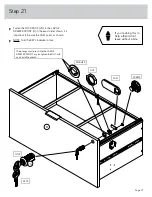
Page 27: ...ant to be sure the CAM points as shown NOTE Turn the KEY clockwise to lock Step 21 H 21J SCREW CAM NUT WASHER LOCK The prongs must press into the LARGE DRAWER FRONT as you tighten the NUT with an adju...

Page 28: ...ER ACTUATOR will be near the top of the RIGHT DRAWER SIDE as shown in diagram 2 Pull the upper wing of the INTERLOCK MECHANISM 34G forward until it clicks into place as shown in diagram 3 Insert the u...

Page 29: ...REWS when finished with adjustments NOTE Please read the back pages of the instruction booklet for important safety information This completes assembly Clean with a damp cloth Wipe dry Step 23 Cam The...

Page 30: ...the heavier items on lower drawers Improperly moving the file cabinet Risk of injury or equipment damage The file cabinet can tip if not moved carefully over obstacles or across a changing floor surf...

Reviews: