background image

 å

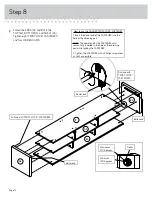
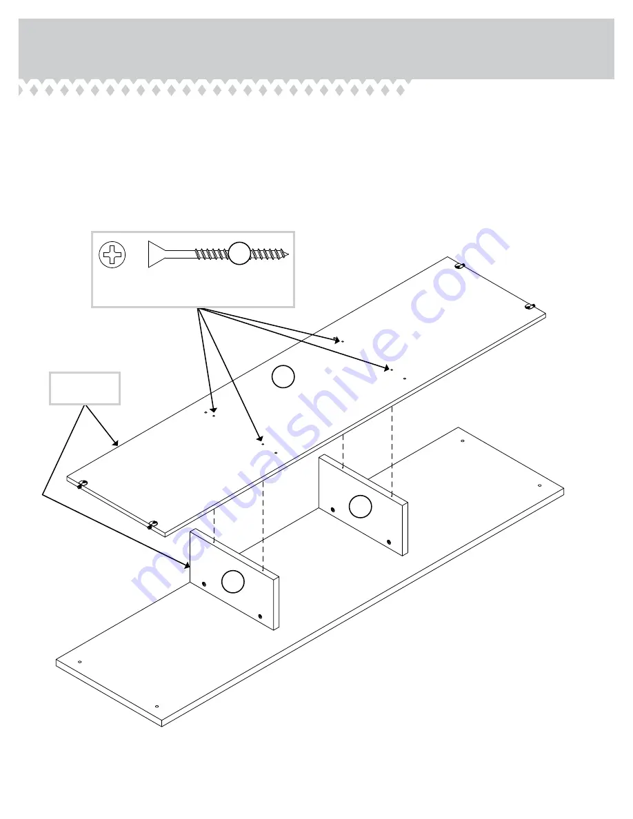
Fasten the SHELF (G3) to the UPRIGHTS (C2). Use four

BLACK 1-7/8" FLAT HEAD SCREWS (2S).

Step 6

BLACK 1-7/8" FLAT HEAD SCREW 

(4 used in this step)

2S

Surf

ace with 

TWIS

T-LOCK

®


FAS

TENERS

C2

C2

G3

Page 10

These edges 

must be even.

Summary of Contents for Hampstead Park 5420834

Page 1: ...INSTRUCTION BOOKLET CONTAINS IMPORTANT SAFETY INFORMATION PLEASE READ AND KEEP FOR FUTURE REFERENCE Hampstead Park TV Stand Credenza Model 5420834 Your holder for all things awesome Teknik www teknikoffice co uk ...

Page 2: ...flat panel televisions weighing less than 95 pounds Never use with a TV that weighs more The size of the television front to back and side to side must fit within the space defined in the diagram Never place the front edge of the TV past the front edge of the TV support shelf or stop molding if equipped Never allow the sides of the TV to extend past the side edges of the TV support surface Be sure...

Page 3: ... E2 F G3 H I J K L M N2 N2 O O O D115 D723 D13 D12 Page 3 Now you know our ABCs M67 A2 RIGHT END 1 B2 LEFT END 1 C2 UPRIGHT 2 D LOWER UPRIGHT 2 D12 RIGHT DRAWER SIDE 3 D13 LEFT DRAWER SIDE 3 D115 DRAWER BACK 3 D723 DRAWER BOTTOM 3 E2 TOP 1 F BOTTOM 1 G3 SHELF 1 H BACK 1 I BRACE 1 J DRAWER FRONT 1 K RIGHT DRAWER FRONT 1 L LEFT DRAWER FRONT 1 M BASE 1 M67 DRAWER BRACE 3 Hidden part using recycled ma...

Page 4: ...D SCREW 38 Page 4 30S BLACK 1 9 16 FLAT HEAD SCREW 15 29M BUMPER CARD 2 4G METAL BRACKET 4 3S GOLD 5 16 FLAT HEAD SCREW 24 PULL 3 154K Refer to step 16 for proper location and application WARNING LABEL 1 3L WARNING For use with televisions weighing 95 lbs 43 kg or less Use with heavier televisions may result in instability causing tip over resulting in death or serious injury Never allow children ...

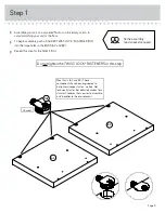
Page 5: ...in assembly push a SAUDER TWIST LOCK FASTENER 10F into the large holes in the ENDS A2 and B2 å Repeat this step for the SHELF G3 Page 5 Some assembly and snacks required Meet Parts A2 and B2 These components have been engineered to be lighter stronger faster well ok Not technically faster But definitely makes for a sturdier Credenza that s easier to assemble and friendlier to the environment ...

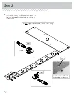
Page 6: ...F and DRAWER BRACES M67 Then insert the metal end of a CAM DOWEL 2F into each HIDDEN CAM Step 2 Insert the metal end of the CAM DOWEL into the HIDDEN CAM Arrow Do not tighten the HIDDEN CAMS in this step 15 used Arrow 1F 2F Arrow 1F 2F C2 C2 D D F Page 6 M67 M67 M67 ...

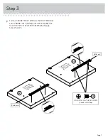
Page 7: ...a CABINET LEFT 35GB to the LEFT END B2 Use four GOLD 5 16 FLAT HEAD SCREWS 3S through holes 1 and 3 1 2 3 Surface with TWIST LOCK FASTENERS Surface with TWIST LOCK FASTENERS B2 A2 Roller end Roller end 1 2 3 Page 7 GOLD 5 16 FLAT HEAD SCREW 4 used in this step 3S ...

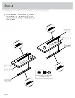
Page 8: ...RIGHTS D Use eight GOLD 5 16 FLAT HEAD SCREWS 3S through holes 1 and 3 Finished edge Finished edge Roller end Roller end Roller end Roller end Surface with HIDDEN CAMS Surface without HIDDEN CAMS D D 1 2 3 1 2 3 1 2 3 1 2 3 Page 8 GOLD 5 16 FLAT HEAD SCREW 8 used in this step 3S ...

Page 9: ...tely tightened HIDDEN CAMS that are not completely tightened may loosen and parts may separate To completely tighten Page 9 Do not stand the unit upright without the BACK fastened The unit may collapse Caution Surface with HIDDEN CAMS Surface with HIDDEN CAMS Surface with holes C2 C2 E2 These edges must be even Part E2 Another sturdier easier friendlier component This hole is closer to this edge ...

Page 10: ...n the SHELF G3 to the UPRIGHTS C2 Use four BLACK 1 7 8 FLAT HEAD SCREWS 2S Step 6 BLACK 1 7 8 FLAT HEAD SCREW 4 used in this step 2S Surface with TWIST LOCK FASTENERS C2 C2 G3 Page 10 These edges must be even ...

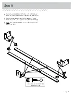
Page 11: ... BOTTOM F to the LOWER UPRIGHTS D Use four BLACK 1 7 8 FLAT HEAD SCREWS 2S Page 11 Finished edge Surface with HIDDEN CAMS Surface with HIDDEN CAMS D D G3 Arrow Minimum 190 degrees Maximum 210 degrees Surface with HIDDEN CAMS F BLACK 1 7 8 FLAT HEAD SCREW 4 used in this step 2S Finished edge ...

Page 12: ...OCK FASTENER 1 Insert the dowel end of the FASTENER into the hole of the adjoining part NOTE The dowel end of the FASTENER must remain fully inserted in the hole of the adjoining part while locking the FASTENER 2 Tighten the FASTENER with a Phillips screwdriver as tight as possible Dowel end A2 B2 E2 F G3 Surface with TWIST LOCK FASTENERS Surface with TWIST LOCK FASTENERS Roller end Roller end Pag...

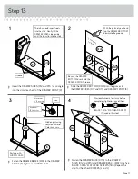
Page 13: ...BLACK 9 16 LARGE HEAD SCREWS 1S å Fasten four METAL BRACKETS 4G to the BRACE I and BASE M Use four BLACK 9 16 LARGE HEAD SCREWS 1S å NOTE Be sure the BRACKETS are even with the edges of the BRACE and BASE 4G 31G 31G BLACK 9 16 LARGE HEAD SCREW 12 used in this step 1S I M Page 13 ...

Page 14: ...BASE and into the BOTTOM å Fasten the SIDE BASES N2 to the CORNER BRACKETS on the BRACE I and BASE M Use eight BLACK 9 16 LARGE HEAD SCREWS 1S Step 10 Page 14 Hey It s starting to look like something BLACK 9 16 LARGE HEAD SCREW 20 used in this step 1S N2 N2 I F M These holes must be closer to this edge The back edges must be even ...

Page 15: ...ite corners of your unit if needed to make it square å Fasten the BACK H to your unit using the NAILS 1N å NOTE Be sure to tap NAILS into the holes that line up over the LOWER UPRIGHTS D These holes must line up over the LOWER UPRIGHTS D NAIL 42 used in this step 1N H Page 15 Do not stand the unit upright without the BACK fastened The unit may collapse Caution ...

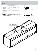
Page 16: ... 1 FLAT HEAD SCREWS 12S å NOTE Be sure to position the MOLDINGS exactly as shown in the enlarged diagram å Repeat this step for the other DRAWER FRONTS J and L Step 12 Surface with grooves K O O O BROWN 1 FLAT HEAD SCREW 36 used in this step 12S Unfinished surface Page 16 ...

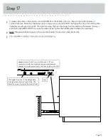
Page 17: ...ep for the other DRAWERS J and L The tabs should insert freely into the slots Gently tilt the DRAWER SIDES side to side until the tabs slip into the slots Unfinished surface 1 2 3 4 Be sure the DRAWER BOTTOM inserts into the DRAWER FRONT groove With the palm of your hand tap the DRAWER BOTTOM down into the groove K D12 D723 D115 D13 K K D12 D13 D12 D13 Groove Page 17 M67 M67 30S Start each screw a...

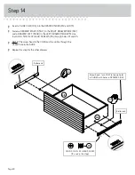
Page 18: ...four GOLD 5 16 FLAT HEAD SCREWS 3S through holes 1 and 3 å NOTE The screw head in the CAM must be visible through the slotted hole in the SLIDE å Repeat this step for the other drawers Step 14 D12 D13 10A 10A Screw head turn CAM to line up holes in SLIDES with holes in DRAWER SIDES Roller end Roller end 1 2 3 1 2 3 Page 18 GOLD 5 16 FLAT HEAD SCREW 12 used in this step 3S ...

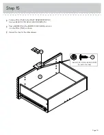
Page 19: ...RAWER FRONT K Use two BLACK 9 16 LARGE HEAD SCREWS 1S å Peel a BUMPER from the BUMPER CARD 29M and stick it on the PULL 154K as shown å Repeat this step for the other drawers 154K 29M K BLACK 9 16 LARGE HEAD SCREW 6 used in this step 1S Page 19 ...

Page 20: ... label Peel off the backing and apply the label as shown in the diagram å NOTE This is a permanent label intended to last for the life of the product Once applied do not try to remove it 95 lbs C2 C2 E2 25 lbs 25 lbs 60 lbs total 25 lbs 3L Page 20 K L J To cover HIDDEN CAMS 13P 4 used WARNING For use with televisions weighing 95 lbs 43 kg or less Use with heavier televisions may result in instabil...

Page 21: ... will help the DRAWER FRONTS line up better when closed Tighten the SCREW when finished with adjustments å NOTE Please read the back pages of the instruction booklet for important safety information å This completes assembly Clean with a damp cloth Wipe dry The higher the screw in the oblong hole the higher your drawer front will be The lower the screw the lower the drawer front Loosen screw 3 a 1...

Page 22: ...and or video equipment may result in death or serious injury due to furniture collapse or over turning onto a child NEVER place a TV on furniture that is not intended to support a TV NEVER exceed the maximum size and weight of the TV shown in the instructions Be sure to apply the TV warning label as shown in the instructions Overloading drawers and shelves may result in furniture that can break or...

Reviews: