background image


å

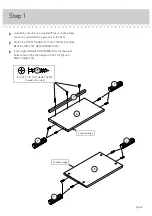
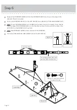
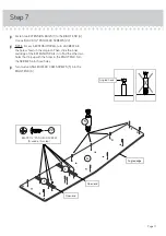
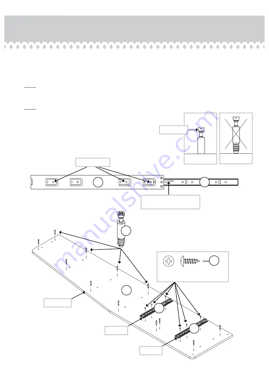
Separate the EXTENSION SLIDES (2) from the EXTENSION RAILS (1) as shown in the diagram. Be
prepared; the parts are greasy.


å

Fasten two EXTENSION RAILS (1) to the LEFT END (B). Use six BLACK 1/2" PAN HEAD SCREWS (22).


å

NOTE: For each EXTENSION RAIL, turn a SCREW into the holes shown in the diagram. Then, slide the
inner cartridge of the EXTENSION RAIL in to fi nd the other two holes that line up with the holes in the 
LEFT END. Turn the SCREWS into those holes.


å

NOTE: The EXTENSION SLIDES will be used later for the DRAWERS.


å

Turn twelve ANGLED HEAD CAM SCREWS (5) into the LEFT END (B).

Step 6

Use these holes.

Push the black lever down and 
pull the SLIDE from the RAIL.

Angled edge

Open end

Open end

Angled head

B

1

1

5

1

2

BLACK 1/2" PAN HEAD SCREW

(6 used in this step)

22

Page 10

Summary of Contents for Hampstead Park Narrow Bookcase 5420283

Page 1: ...office co uk Narrow Bookcase Hampstead Park Collection Model 5420283 NOTE THIS INSTRUCTION BOOKLET CONTAINS IMPORTANT SAFETY INFORMATION PLEASE READ AND KEEP FOR FUTURE REFERENCE The stories of your l...

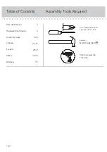
Page 2: ...quired Part Identi cation Hardware Identi cation Assembly Steps Fran ais Espa ol Safety Warranty Hammer Not actual size No 2 Phillips Screwdriver Tip Shown Actual Size Skip the power trip This time 3...

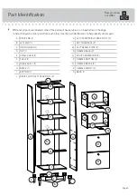
Page 3: ...fy similar parts Now you know our ABCs A RIGHT END 1 B LEFT END 1 C TOP MOLDING 1 D TOP 1 E SMALL SHELF 1 F SHELF 1 G LARGE SHELF 1 H BRACE 1 I BOTTOM 1 J RIGHT FRONT LEFT REAR FOOT 2 K LEFT FRONT RIG...

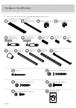
Page 4: ...ngled head Straight head 5 ANGLED HEAD CAM SCREW 36 6 STRAIGHT HEAD CAM SCREW 12 7 LONG WOOD DOWEL 30 8 SHORT WOOD DOWEL 4 9 COVER CARD 1 10 KNOB 2 11 LONG FILE GLIDE 2 12 SHORT FILE GLIDE 4 13 FRONT...

Page 5: ...or the oor Fasten the TOP MOLDING C to the TOP D Use three BLACK 1 1 8 FLAT HEAD SCREWS 20 Insert eight LONG WOOD DOWELS 7 into the exact holes shown in the short edges of the TOP D and SMALL SHELF E...

Page 6: ...Insert eight LONG WOOD DOWELS 7 into the exact holes shown in the short edges of the SHELVES F and G Step 2 7 7 7 7 Rounded edge Rounded edge F G Page 6 Some assembly and snacks required...

Page 7: ...Turn eight ANGLED CAM SCREWS 5 into the small holes in the BOTTOM I Insert four LONG WOOD DOWELS 7 into the edges of the BOTTOM I Step 3 Finished edge 7 7 5 Angled head I Page 7...

Page 8: ...the BOTTOM BRACE L Insert two LARGE HIDDEN CAMS 3 into the holes in the BOTTOM BRACE L as shown Fasten the FEET J and K to the BOTTOM BRACE L Tighten two LARGE HIDDEN CAMS Repeat this step for the ot...

Page 9: ...3 completely into the holes in the BOTTOM BRACE L and FEET J and K as shown Fasten the FEET J and K and BOTTOM BRACES L to the BOTTOM I Tighten eight LARGE HIDDEN CAMS Step 5 Angled head 3 2 1 The ar...

Page 10: ...gram Then slide the inner cartridge of the EXTENSION RAIL in to nd the other two holes that line up with the holes in the LEFT END Turn the SCREWS into those holes NOTE The EXTENSION SLIDES will be us...

Page 11: ...n in the diagram Then slide the inner cartridge of the EXTENSION RAIL in to nd the other two holes that line up with the holes in the RIGHT END Turn the SCREWS into those holes Turn twelve ANGLED HEAD...

Page 12: ...SHELVES E F and G BRACE H and BOTTOM I Tighten twelve LARGE HIDDEN CAMS NOTE Be sure the WOOD DOWELS in the TOP SHELVES BOTTOM and FEET insert into the LEFT END Step 8 Angled edge 3 2 1 The arrow must...

Page 13: ...d BOTTOM I Fasten the RIGHT END A to the TOP D SHELVES E F and G BRACE H BRACE H and BOTTOM I Tighten twelve LARGE HIDDEN CAMS NOTE Be sure the WOOD DOWELS in the TOP SHELVES BOTTOM and FEET insert in...

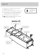
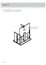
Page 14: ...nit if needed to make it square Fasten the BACK S to your unit using fty NAILS 17 NOTE Perforations have been provided for access through the BACK Carefully cut out the holes needed Step 10 Do not use...

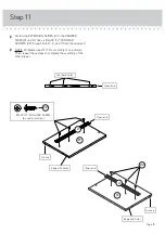
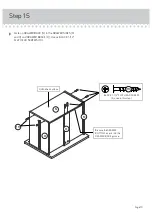
Page 15: ...6 and 9 from the open end NOTE Complete steps 11 17 for assembly of one drawer Then repeat these steps to complete the assembly of the other drawer Step 11 Use these holes Open end Groove Open end Gro...

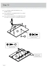
Page 16: ...ACK 7 8 MACHINE SCREW 21 Fasten a FRONT FILE GLIDE 13 to the DRAWER FRONT R as shown below Use four BLACK 1 2 PAN HEAD SCREWS 22 Step 12 BLACK 1 2 PAN HEAD SCREW 8 used in this step 22 R The ange is f...

Page 17: ...HIDDEN CAMS 4 into one DRAWER SIDE M and O and a DRAWER BRACE Q Fasten the DRAWER SIDES M and O and DRAWER BRACE Q to the DRAWER FRONT R Tighten six SMALL HIDDEN CAMS Step 13 4 3 2 1 The arrow must po...

Page 18: ...Slide a DRAWER BOTTOM P into the grooves in the DRAWER SIDES M and O and DRAWER FRONT R Step 14 Page 18 Un nished surface P M R O...

Page 19: ...WER SIDES M and O and DRAWER BRACE Q Use six BLACK 1 1 2 FLAT HEAD SCREWS 19 Step 15 Page 19 Un nished surface M N Q O Be sure the DRAWER BOTTOM inserts into the DRAWER BACK groove BLACK 1 1 2 FLAT HE...

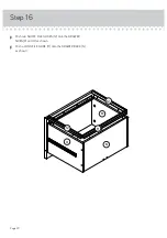
Page 20: ...Push two SHORT FILE GLIDES 12 onto the DRAWER SIDES M and O as shown Push a LONG FILE GLIDE 11 onto the DRAWER BACK N as shown Step 16 Page 20 M 12 11 12 N O...

Page 21: ...Push two FILE HANGERS 14 onto the FRONT FILE GLIDE 13 and LONG FILE GLIDE 11 Repeat steps 11 17 Step 17 Page 21 14 13 11 14 Almost time to celebrate With a nap...

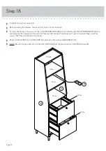
Page 22: ...the unit and push the drawers into the unit until they are fully inserted The drawers will push in hard until they are all the way in then they will slide in and out easier Peel a CAM COVER from COVE...

Page 23: ...ce your unit in its nal location against a wall Follow the instructions included in the KIT to fasten your unit to the wall NOTE Please read the back pages of the instruction booklet for important saf...

Page 24: ...r or break if improperly moved Physical injury Furniture can be very heavy Unload shelves from top to bottom before moving the furniture Do not push furniture especially on a carpeted oor Have a frien...

Reviews: