background image

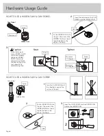
Hardware Usage Guide

Start

Tighten

Arrow

Minimum

190 degrees


Caution

Risk of damage or 

injury. HIDDEN CAMS 

must be completely 

tightened. HIDDEN 

CAMS that are not 

completely tightened 

may loosen, and parts 

may separate. To 

completely tighten:

Arrow

Maximum

210 degrees

3.

Start

Tighten

Arrow

Minimum

190 degrees


Caution

Risk of damage or 

injury. HIDDEN CAMS 

must be completely 

tightened. HIDDEN 

CAMS that are not 

completely tightened 

may loosen, and parts 

may separate. To 

completely tighten:

Arrow

Maximum

210 degrees

HOW TO USE A HIDDEN CAM & CAM DOWEL

Hole

Hidden Cam

Cam Dowel

2.

Hole

Hidden Cam

Cam Dowel

Insert the metal end of the CAM
DOWEL into the HIDDEN CAM.

Metal end

Arrow

1.

Push a HIDDEN CAM into
the part. The arrow in the
HIDDEN CAM must point
toward the hole in the
edge of the board.

Cam Screw

Hidden Cam

Arrow

Push a HIDDEN CAM into 
the part. The arrow in the 
HIDDEN CAM must point 
toward the hole in the 
edge of the board.

Hole

2.

3.

1

2

Insert the CAM SCREW into the HIDDEN CAM. 
Tighten the HIDDEN CAM.

HOW TO USE A HIDDEN CAM & CAM SCREW

Turn the CAM SCREW until 
the shoulder is against the 
surface of the part.

1.

Page 6

Summary of Contents for Home Study 5426616

Page 1: ... INSTRUCTION BOOKLET CONTAINS IMPORTANT SAFETY INFORMATION PLEASE READ AND KEEP FOR FUTURE REFERENCE TV Stand Home Study Collection Model 5426616 Your holder for all things awesome Teknik www teknikoffice co uk ...

Page 2: ...ject to tip over Check the size and weight of your TV Compare it to the diagram below before you begin assembly This Sauder unit is designed for use with flat panel televisions weighing less than 50 pounds Never use with a TV that weighs more The size of the television front to back and side to side must fit within the space defined in the diagram Never place the front edge of the TV past the front e...

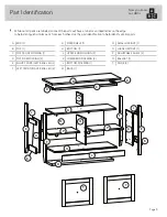
Page 3: ...help identify similar parts Now you know our ABCs A END 2 B TOP 1 C TOP FRONT MOLDING 1 D TOP SIDE MOLDING 2 E RIGHT FRONT LEFT REAR LEG 2 F LEFT FRONT RIGHT REAR LEG 2 G FIXED SHELF 1 H BOTTOM 1 J UPPER END MOLDING 2 K LOWER END MOLDING 2 L BOTTOM MOLDING 1 M BACK 1 N SMALL UPRIGHT 1 O LARGE UPRIGHT 1 P ADJUSTABLE SHELF 2 Q BALLAST 1 T DOOR 2 A A B C D E F G H L M N O P Q J K P T T F E D K J Page...

Page 4: ...ren to climb on audio video furniture Refer to instruction book for complete safety information Note This is a permanent label Do not try to remove Surface will be damaged 11 18 5 2 4 9 2 8 524928 WARNING LABEL 1 1L Refer to the last step for proper location and application APPLIQUE CARD 4 100P FELT DISC CARD 1 1M ANGLE BRACKET 8 27G WASHER 2 10I METAL PIN 10 1R CAM SCREW 8 8F PULL 2 22K WOOD DOWE...

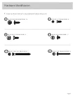
Page 5: ... You may receive extra hardware with your unit BLACK 9 16 LARGE HEAD SCREW 16 1S SILVER 1 4 MACHINE SCREW 2 61S BLACK 1 2 FLAT HEAD SCREW 8 11S BLACK 9 16 FLAT HEAD SCREW 8 32S BLACK 1 15 16 FLAT HEAD SCREW 7 113S BLACK 1 3 8 PAN HEAD SCREW 6 118S Page 5 ...

Page 6: ...te To completely tighten Arrow Maximum 210 degrees HOW TO USE A HIDDEN CAM CAM DOWEL Hole Hidden Cam Cam Dowel 2 Hole Hidden Cam Cam Dowel Insert the metal end of the CAM DOWEL into the HIDDEN CAM Metal end Arrow 1 Push a HIDDEN CAM into the part The arrow in the HIDDEN CAM must point toward the hole in the edge of the board Cam Screw Hidden Cam Arrow Push a HIDDEN CAM into the part The arrow in t...

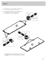
Page 7: ...ratching your unit or the floor å Push six HIDDEN CAMS 1F into the FIXED SHELF G and BACK M Then insert the metal end of a CAM DOWEL 2F into each HIDDEN CAM G M Do not tighten the HIDDEN CAMS in this step Arrow 1F 2F 6 used Metal end 1F 2F Arrow Metal end 1F 2F Metal end Arrow Page 7 ...

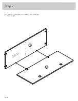
Page 8: ...å Fasten the FIXED SHELF G to the BACK M Tighten two HIDDEN CAMS Step 2 G M Page 8 Surface with HIDDEN CAMS ...

Page 9: ...å Fasten the SMALL UPRIGHT N to the FIXED SHELF G Use two BLACK 1 15 16 FLAT HEAD SCREWS 113S Step 3 G N BLACK 1 15 16 FLAT HEAD SCREW 2 used in this step 113S Page 9 Some assembly and snacks required ...

Page 10: ...Push two HIDDEN CAMS 1F into the LARGE UPRIGHT O Then insert the metal end of a CAM DOWEL 2F into each HIDDEN CAM Step 4 O Do not tighten the HIDDEN CAMS in this step Arrow 1F 2F 2 used Metal end Page 10 ...

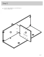
Page 11: ...å Fasten the LARGE UPRIGHT O to the FIXED SHELF G Tighten two HIDDEN CAMS Step 5 G O Surface without HIDDEN CAMS Page 11 ...

Page 12: ...r HIDDEN CAMS 1F into the BOTTOM H Then insert the metal end of a CAM DOWEL 2F into each HIDDEN CAM Step 6 H Do not tighten the HIDDEN CAMS in this step 1F 2F Metal end Arrow 1F 2F Arrow 4 used Metal end Page 12 ...

Page 13: ...å Fasten the BOTTOM H to the BACK M and LARGE UPRIGHT O Use five BLACK 1 15 16 FLAT HEAD SCREWS 113S Step 7 M O H BLACK 1 15 16 FLAT HEAD SCREW 5 used in this step 113S Page 13 ...

Page 14: ... Slide a BOTTOM MOLDING L onto the notched edge of a BOTTOM H å U S Patent No 5 499 886 Step 8 Slide the BOTTOM MOLDING L onto the notched edge L The groove is closer to this edge Notched edge H Page 14 ...

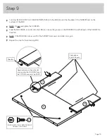
Page 15: ...END A Line up the grooves in the MOLDINGS over the heads of the SCREWS in the END å NOTE If the MOLDING comes up off of the SCREWS remove it and slide it on again å Repeat this step for the remaining END Step 9 A J K BLACK 9 16 FLAT HEAD SCREW 8 used in this step 32S Shoulder Apply pressure with your hands as you guide the MOLDINGS over the SCREWS and onto the ENDS These edges should be even Page ...

Page 16: ...own å Push two HIDDEN CAMS 1F into the LEGS E and F Then insert the metal end of a CAM DOWEL 2F into each HIDDEN CAM å Repeat this step for the remaining LEGS F F E E 15F 15F 8F 8F Do not tighten the HIDDEN CAMS in this step Arrow 1F 2F 2 used Metal end F L I P OVER F L I P OVER Page 16 Now might be a good time to refresh your drink ...

Page 17: ...nto the END A å Fasten the LEGS E and F Tighten four HIDDEN CAMS å NOTE Be sure the WOOD DOWELS in the LEGS insert into the ENDS å Repeat this step for the remaining END and LEGS E F A A 1F Arrow 1F Arrow 15F Angled edge Surface with HIDDEN CAMS Surface with HIDDEN CAMS Page 17 ...

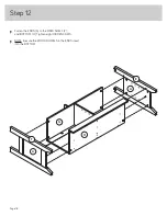
Page 18: ...å Fasten the ENDS A to the FIXED SHELF F and BOTTOM H Tighten eight HIDDEN CAMS å NOTE Be sure the WOOD DOWELS in the ENDS insert into the BOTTOM Step 12 H G A A E F Page 18 ...

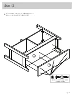
Page 19: ...å Fasten the BALLAST Q to the BOTTOM H Use six BLACK 1 3 8 PAN HEAD SCREWS 118S Step 13 H Q BLACK 1 3 8 PAN HEAD SCREW 6 used in this step 118S Page 19 ...

Page 20: ...S 27G to the TOP B Use eight BLACK 9 16 LARGE HEAD SCREWS 1S through the center of the ANGLE BRACKET hole å Push two METAL PINS 1R into the TOP B Step 14 BLACK 9 16 LARGE HEAD SCREW 8 used in this step 1S 27G B 27G 27G Page 20 1R ...

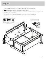
Page 21: ...PRIGHT å Fasten the MOLDINGS C and D to the TOP B Use eight BLACK 9 16 LARGE HEAD SCREWS 1S through the ANGLE BRACKETS and into the MOLDINGS å Peel APPLIQUES from the APPLIQUE CARDS 100P and stick them onto each visible HIDDEN CAM Step 15 B E F F E D D C N 24 used To cover HIDDEN CAMS 100P Page 21 BLACK 9 16 LARGE HEAD SCREW 8 used in this step 1S ...

Page 22: ...å Fasten two HINGES 14H to one of the DOORS T Use four BLACK 1 2 FLAT HEAD SCREWS 11S å Repeat this step for the remaining door Step 16 14H BLACK 1 2 FLAT HEAD SCREW 8 used in this step 11S T Page 22 ...

Page 23: ...in the HINGES You should start each SCREW a few turns before completely tightening any of them å Fasten a PULL 22K to the DOOR T Use a WASHER 10I and a SILVER 1 4 MACHINE SCREW 61S å Peel two FELT DISKS from the FELT DISK CARD 1M to the DOOR T where it comes in contact with the LARGE UPRIGHT O å Repeat this step for the other DOOR T å See the next step for DOOR adjustments Step 17 T A Mounting scr...

Page 24: ...g screw in or out å To adjust the DOORS up and down vertical loosen both vertical adjustment screws Move the DOORS up or down to the desired location Tighten the screws after making adjustments å To adjust the DOORS in or out depth loosen the mounting screw one turn and move the DOORS in or out as needed Tighten the mounting screw after making adjustments Step 18 vertical adjustment Adjusting scre...

Page 25: ...R Insert the METAL PINS into the hole locations of your choice in the ENDS A and LARGE UPRIGHTS O Set the ADJUSTABLE SHELVES P onto the METAL PINS å Insert the GROMMETS 10P into the large holes in the BACK M Step 19 A O A M 8 used 2R 1R P P 10P Page 25 ...

Page 26: ...22 6 kg or les s Us e wit h heavier televisio ns ma y res ult in ins tab ility causing tip over res ulting in death or serious inju ry Never allo w childr en to clim b on audio vid eo fur niture Re fer to ins tru ctio n book for comp lete safety inform ation No te Th is is a perm anent lab el Do not try to rem ove Su rfa ce wil l be dama ged 11 18 5 2 4 9 2 8 524928 1L WARNING For use with televis...

Page 27: ...video equipment may result in death or serious injury due to furniture collapse or over turning onto a child NEVER place a TV on furniture that is not intended to support a TV NEVER exceed the maximum size and weight of the TV shown in the instructions Be sure to apply the TV warning label as shown in the instructions Overloading drawers and shelves may result in furniture that can break or sag or...

Reviews: