background image

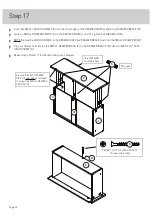
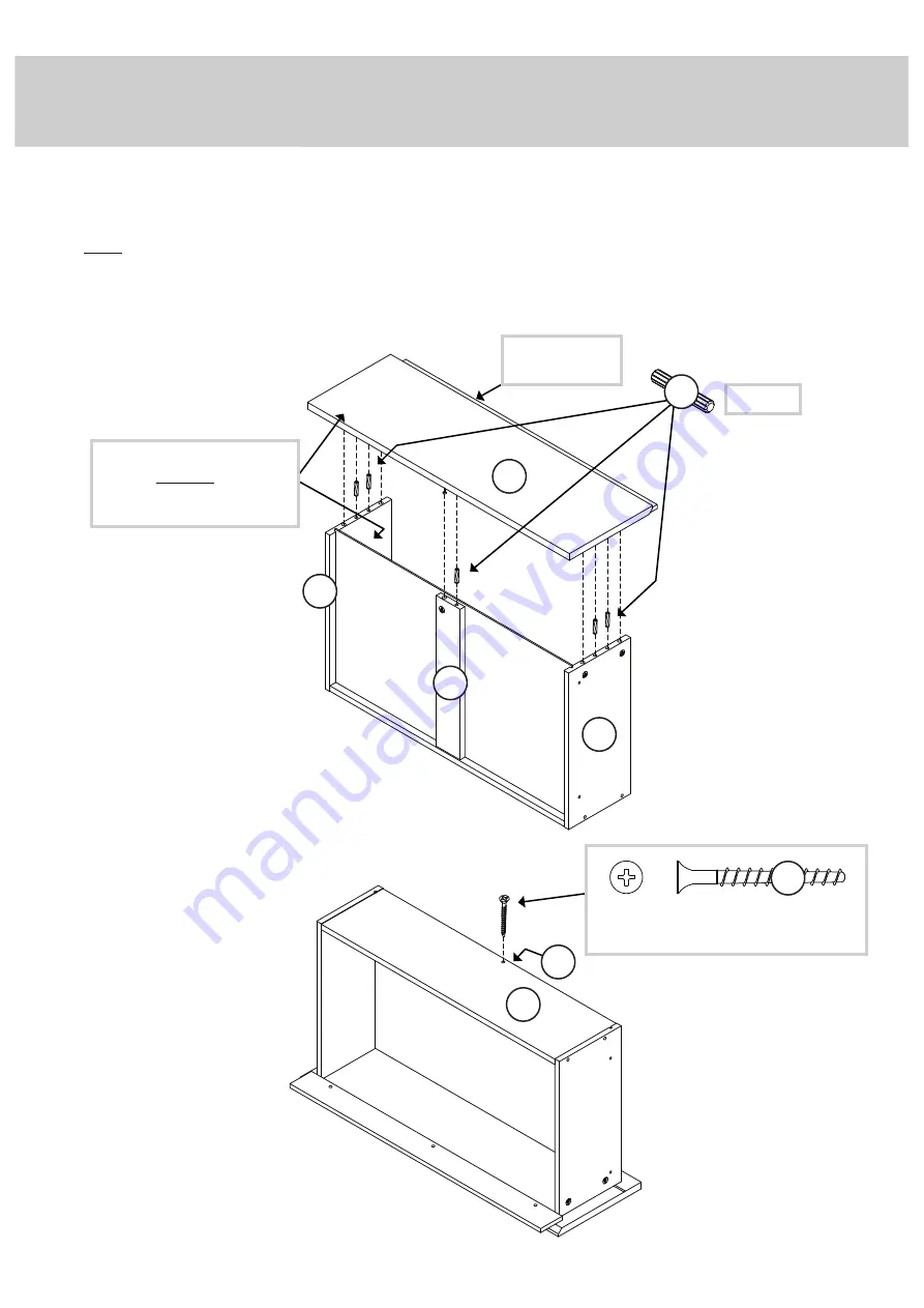
Step 17

 å

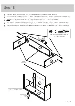
Insert fi ve SMALL WOOD DOWELS (5) into the short edges of the DRAWER SIDES (J and V) and DRAWER BRACE (M).

 å

Fasten a SMALL DRAWER FRONT (H) to the DRAWER SIDES (J and V). Tighten fi ve HIDDEN CAMS.

 å

NOTE: Be sure the WOOD DOWELS in the DRAWER SIDES and DRAWER BRACE insert into the SMALL DRAWER FRONT.

 å

Flip your drawer over. Fasten the SMALL DRAWER BACK (K) to the DRAWER BRACE (M). Use a SILVER 1-1/2" FLAT
HEAD SCREW (9). 

 å

Repeat steps 16 and 17 for the remaining small drawers.

Be sure the LEFT DRAWER 
SIDE (H) with label is fastened 
to one of the SMALL DRAWER 
FRONTS (H).

SILVER 1-1/2" FLAT HEAD SCREW

(3 used in this step)

9

(15 used)

5

J

V

M

H

K

The MOLDING 
should be here.

Page 22

M

Summary of Contents for Hudson 5425709

Page 1: ...NSTRUCTION BOOKLET CONTAINS IMPORTANT SAFETY INFORMATION PLEASE READ AND KEEP FOR FUTURE REFERENCE Don t get caught with your pants on the ground Hudson 6 DrawerDresser Model 5425709 Teknik www teknikoffice co uk ...

Page 2: ...GHT END 1 C UPRIGHT 1 D TOP 1 E BOTTOM 1 F SKIRT 2 G BRACE 1 H SMALL DRAWER FRONT 3 J RIGHT DRAWER SIDE 6 K SMALL DRAWER BACK 3 L SMALL DRAWER BOTTOM 3 M DRAWER BRACE 6 N SMALL DRAWER FRONT MOLDING 3 O LARGE DRAWER FRONT 3 P LARGE DRAWER BACK 3 Q LARGE DRAWER BOTTOM 3 R LARGE DRAWER FRONT MOLDING 3 S RIGHT BACK 1 T LEFT BACK 1 U LARGE BACK 1 V LEFT DRAWER SIDE 6 1 with label Part Identification Ele...

Page 3: ...l or an inked letter on the edge to help distinguish similar parts from each other Use this part identification to help identify similar parts Now you know our ABCs Part Identification A B C D E F F G H H H J J J K K L L M M N N N O O O P P Q R R R S T U V V V V V Page 3 ...

Page 4: ...WEL 60 5 35AA UNIVERSAL CABINET RAIL 12 35AC DRAWER RIGHT 6 35AD DRAWER LEFT 6 SILVER 1 1 2 FLAT HEAD SCREW 30 9 BLACK 3 8 FLAT HEAD SCREW 48 11 BLACK 3 4 FLAT HEAD SCREW 18 10 FURNITURE TIPPING RESTRAINT KIT 2 98 SILVER 2 FLAT HEAD SCREW 10 8 NAIL 20 6 APPLIQUE CARD 3 7 Page 4 CAM SCREW 44 3 LARGE HIDDEN CAM 14 1 SMALL HIDDEN CAM 30 2 ...

Page 5: ... Turn the CAM SCREW or gently tap the CAM DOWEL until the shoulder is against the surface of the part 1 Hidden Cam Hidden Cam Arrow Push a HIDDEN CAM into the part The arrow in the HIDDEN CAM must point toward the hole in the edge of the board Hole 2 3 1 2 Insert the CAM SCREW or CAM DOWEL into the HIDDEN CAM Tighten the HIDDEN CAM Page 5 ...

Page 6: ...å Fasten six UNIVERSAL CABINET RAILS 35AA to the ENDS A and B Use twelve BLACK 3 8 FLAT HEAD SCREWS 11 through holes 1 and 3 å patent pending glide system A B BLACK 3 8 FLAT HEAD SCREW 12 used for the RAILS 11 1 2 3 1 2 3 1 2 3 1 2 3 1 2 3 1 2 3 Edge with more holes Edge with more holes Glide end Glide end Page 6 ...

Page 7: ...Step 2 A B å Turn six CAM SCREWS 3 into the exact holes shown in the ENDS A and B 3 Page 7 Just think The sooner you do this the sooner you do something else ...

Page 8: ... the UPRIGHT C Use six BLACK 3 8 FLAT HEAD SCREWS 11 through holes 1 and 3 å Turn a CAM SCREW 3 into the UPRIGHT C å patent pending glide system BLACK 3 8 FLAT HEAD SCREW 6 used for the RAILS 11 1 2 3 1 2 3 1 2 3 Edge with more holes Glide end C 3 Page 8 ...

Page 9: ...RAILS 35AA to the UPRIGHT C Use six BLACK 3 8 FLAT HEAD SCREWS 11 through holes 1 and 3 å Turn a CAM SCREW 3 into the UPRIGHT C å patent pending glide system BLACK 3 8 FLAT HEAD SCREW 6 used for the RAILS 11 1 2 3 1 2 3 1 2 3 Edge with more holes Glide end C 3 Page 9 ...

Page 10: ...Step 5 S T E C A B å Push fourteen LARGE HIDDEN CAMS 1 into the ENDS A and B UPRIGHT C BACKS S and T and BOTTOM E Page 10 14 used Arrow 1 1 Arrow 1 Arrow ...

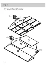
Page 11: ...h the SKIRTS F onto the LARGE WOOD DOWELS 4 in the BRACE G å Insert ten LARGE WOOD DOWELS 4 into the BOTTOM E å Push the SKIRTS F and BRACE G onto the LARGE WOOD DOWELS 4 in the BOTTOM E 4 Edge without holes Edge without holes F F F F G G E 4 used 10 used 4 Page 11 ...

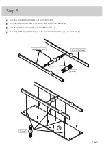
Page 12: ...å Turn the BOTTOM on its long edge å Fasten the SKIRTS F to the BOTTOM E Use eight SILVER 2 FLAT HEAD SCREWS 8 Step 7 SILVER 2 FLAT HEAD SCREW 8 used in this step 8 E F F Page 12 ...

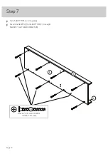
Page 13: ...C å Fasten the BACKS S and T to the UPRIGHT C Tighten two HIDDEN CAMS å NOTE Be sure the WOOD DOWELS in the UPRIGHT insert into the BACKS S and T Step 8 S T C 4 S u r f a c e w i t h H I D D E N C A M S S u r f a c e w i t h H I D D E N C A M S Page 13 ...

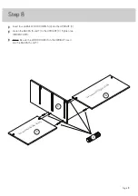
Page 14: ...and UPRIGHT C å Fasten the BOTTOM E to the BACKS S and T and UPRIGHT C Use two SILVER 2 FLAT HEAD SCREWS 8 å NOTE Be sure the WOOD DOWELS in the BACKS and UPRIGHT insert into the BOTTOM Step 9 4 SILVER 2 FLAT HEAD SCREW 2 used in this step 8 E S T C Page 14 ...

Page 15: ...ten the RIGHT END B to the BOTTOM E SKIRTS F and RIGHT BACK S Tighten three HIDDEN CAMS å Fasten the LEFT END A to the BOTTOM E SKIRTS F and LEFT BACK T Tighten three HIDDEN CAMS Step 10 E S T A B 4 16 used Page 15 Side Step Make nachos Optional but recommended F F ...

Page 16: ...T KITS 98 and fasten the SAFETY STRAPS to the TOP D Use the provided short screws å NOTE Position the SAFETY STRAPS exactly as shown å Turn six CAM SCREWS 3 into the TOP D Step 11 Use the short screws through the holes in the straps and into the surface of the TOP D 98 Safety strap D x 2 Page 16 6 used 3 ...

Page 17: ...ere D å Insert six WOOD DOWELS 4 into the ENDS A and B and UPRIGHT C å Fasten the TOP D to the ENDS A and B and UPRIGHT C Tighten six HIDDEN CAMS å NOTE Be sure the WOOD DOWELS in the ENDS and UPRIGHT insert into the TOP 4 4 A B C Page 17 ...

Page 18: ...ide edges of the BACK U Push on opposite corners of your unit if needed to make it square å Fasten the BACK U to your unit using the NAILS 6 å NOTE Be sure to tap NAILS into the holes that line up over the UPRIGHT C Do not stand the unit upright without the BACK fastened The unit may collapse Caution NAIL 20 used for the BACK 6 U These holes must line up over the UPRIGHT C C Page 18 Push the SAFET...

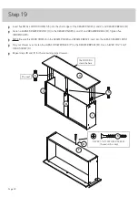
Page 19: ...å Push five SMALL HIDDEN CAMS 2 into the DRAWER SIDES J and V and BRACES M å Repeat this step for the remaining DRAWER SIDES J and V and BRACES M Step 14 J V M Arrow 30 used Page 19 2 ...

Page 20: ...RONT H and the LARGE DRAWER FRONT MOLDING R to the LARGE DRAWER FRONT O Use six BLACK 3 4 FLAT HEAD SCREWS 10 å Repeat this step twice Step 15 H O N R 30 used BLACK 3 4 FLAT HEAD SCREW 18 used in this step 10 The MOLDING with hang over the angled edge of the DRAWER FRONT The MOLDING with hang over the angled edge of the DRAWER FRONT Page 20 3 ...

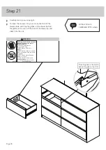
Page 21: ...e SMALL DRAWER BACK insert into the DRAWER SIDES å Slide a SMALL DRAWER BOTTOM L into the grooves in the DRAWER SIDES J and V and SMALL DRAWER BACK K å Insert a SMALL WOOD DOWEL 5 into the exact hole shown in the SMALL DRAWER BACK K Push the BRACE M onto the WOOD DOWEL in the SMALL BACK J K V 12 used M K 5 SILVER 1 1 2 FLAT HEAD SCREW 12 used in this step 9 Unfinished surface Surface with HIDDEN CA...

Page 22: ...DRAWER SIDES and DRAWER BRACE insert into the SMALL DRAWER FRONT å Flip your drawer over Fasten the SMALL DRAWER BACK K to the DRAWER BRACE M Use a SILVER 1 1 2 FLAT HEAD SCREW 9 å Repeat steps 16 and 17 for the remaining small drawers Be sure the LEFT DRAWER SIDE H with label is fastened to one of the SMALL DRAWER FRONTS H SILVER 1 1 2 FLAT HEAD SCREW 3 used in this step 9 15 used 5 J V M H K The...

Page 23: ...e LARGE DRAWER BACK insert into the DRAWER SIDES å Slide a LARGE DRAWER BOTTOM Q into the grooves in the DRAWER SIDES V and J and LARGE DRAWER BACK P å Insert a SMALL WOOD DOWEL 5 into exact hole shown in the LARGE DRAWER BACK P Push the BRACE M onto the WOOD DOWEL in the LARGE BACK J J P V V 12 used M P 5 SILVER 1 1 2 FLAT HEAD SCREW 12 used in this step 9 Unfinished surface Surface with HIDDEN CA...

Page 24: ...ve HIDDEN CAMS å NOTE Be sure the WOOD DOWELS in the DRAWER SIDES and DRAWER BRACE insert into the LARGE DRAWER FRONT å Flip your drawer over Fasten the LARGE DRAWER BACK P to the DRAWER BRACE M Use a SILVER 1 1 2 FLAT HEAD SCREW 9 å Repeat steps 18 and 19 for the remaining large drawers 15 used 5 5 O P J V SILVER 1 1 2 FLAT HEAD SCREW 3 used in this step 9 M M The MOLDING should be here Page 24 ...

Page 25: ...REWS 11 through holes 1 and 2 å NOTE The glides are not intended to rotate å Peel APPLIQUES from the APPLIQUE CARDS 7 and stick them on each visible HIDDEN CAM å Repeat this step for the remaining drawers Drawer Slide Center the screw in the oval hole Glide end Glide end 1 2 J V 7 BLACK 3 8 FLAT HEAD SCREW 24 used for the SLIDES 11 Page 25 3 used ...

Page 26: ...les TOU JOU RS insta ller le disp ositi f anti basc ulem ent fourn i NE JAM AIS mett re de télév iseu r sur ce prod uit NE JAM AIS laiss er les enfa nts se tenir debo ut mon ter sur les tiroir s les porte s ou les table ttes ni s y susp endr e NE JAM AIS ouvr ir plus d un tiroir à la fois Plac er les artic les plus lourd s dans les tiroir s infér ieurs Cett e étiqu ette est perm anen te Ne pas l e...

Page 27: ...sult in death or serious injury due to furniture collapse or tip over NEVER place a TV on furniture that is not intended to support a TV This product is not designed to support a television unless a TV warning label is included and the instructions specifically state the size and weight of the television Overloading drawers and shelves may result in furniture that can break or sag or tip over which...

Reviews: