background image

Hardware Identifi cation


å

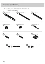
Screws are shown actual size. You may receive extra hardware with your unit.

Page 4

SILVER 1-1/2" FLAT HEAD SCREW - 4

10

SMALL WOOD 
DOWEL - 8

8

LARGE WOOD 
DOWEL - 20

7

APPLIQUE - 10

9

FILE GLIDE - 2

3

(EXTENSION SET SHOWN SEPARATED)

CAM SCREW - 22

6

LARGE HIDDEN

CAM - 18

4

SMALL HIDDEN

CAM - 4

5

SILVER 3/8" FLAT HEAD SCREW - 10

11

1

EXTENSION RAIL - 2

2

EXTENSION SLIDE - 2

Summary of Contents for Hudson 5425825

Page 1: ...NOTE THIS INSTRUCTION BOOKLET CONTAINS IMPORTANT SAFETY INFORMATION PLEASE READ AND KEEP FOR FUTURE REFERENCE Hudson Beside Night Stand Model 5425825 It stands You sleep Teknik www teknikoffice co uk ...

Page 2: ...rdware Identification Assembly Steps Français Español Safety Warranty No 2 Phillips Screwdriver Tip Shown Actual Size Table of Contents Assembly Tools Required Skip the power trip This time 3 4 5 15 16 18 19 21 22 23 Page 2 ...

Page 3: ...elp distinguish similar parts from each other Use this part identification to help identify similar parts Now you know our ABCs A LEFT END 1 B RIGHT END 1 C BOTTOM 1 D TOP 1 E SHELF 1 F SKIRT 1 G DRAWER FRONT 1 H LEFT DRAWER SIDE 1 J DRAWER BACK 1 K DRAWER BOTTOM 1 L BACK 1 M RIGHT DRAWER SIDE 1 Page 3 A B C D E F G H J K L M ...

Page 4: ...with your unit Page 4 SILVER 1 1 2 FLAT HEAD SCREW 4 10 SMALL WOOD DOWEL 8 8 LARGE WOOD DOWEL 20 7 APPLIQUE 10 9 FILE GLIDE 2 3 EXTENSION SET SHOWN SEPARATED CAM SCREW 22 6 LARGE HIDDEN CAM 18 4 SMALL HIDDEN CAM 4 5 SILVER 3 8 FLAT HEAD SCREW 10 11 1 EXTENSION RAIL 2 2 EXTENSION SLIDE 2 ...

Page 5: ... Turn the CAM SCREW or gently tap the CAM DOWEL until the shoulder is against the surface of the part 1 Hidden Cam Hidden Cam Arrow Push a HIDDEN CAM into the part The arrow in the HIDDEN CAM must point toward the hole in the edge of the board Hole 2 3 1 2 Insert the CAM SCREW or CAM DOWEL into the HIDDEN CAM Tighten the HIDDEN CAM Page 5 ...

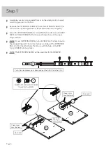
Page 6: ...own in the upper diagram below å NOTE For each EXTENSION RAIL turn a SCREW into the hole shown in the enlarged diagram Then slide the inner cartridge of the EXTENSION RAIL in to find the other holes that line up with the holes in the END Turn a SCREW into these holes å NOTE The EXTENSION SLIDES will be used later for the DRAWER Page 6 A B 1 2 Open end Open end Push the release lever up or down and ...

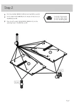
Page 7: ...A and B å Turn fourteen CAM SCREWS 6 into the exact holes shown in the ENDS A and B å Then insert fourteen LARGE WOOD DOWELS 7 into the remaining holes in the ENDS A and B A B Arrow 4 6 7 14 used Just think The sooner you do this the sooner you do something else ...

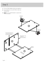
Page 8: ...ACK L to the LEFT END A Tighten two HIDDEN CAMS å NOTE Be sure the WOOD DOWELS in the LEFT END insert into the BACK Step 3 Page 8 Notch L A L S u r f a c e w i t h H I D D E N C A M S Edge with HIDDEN CAMS Arrow 4 Arrow 4 The EXTENSION RAIL is closer to this edge ...

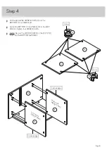
Page 9: ...ten the BOTTOM C and SHELF E to the LEFT END A Tighten four HIDDEN CAMS å NOTE Be sure the WOOD DOWELS in the LEFT END insert into the BOTTOM and SHELF Step 4 Page 9 E A C C Arrow 4 Arrow 4 Surface with HIDDEN CAMS E Surface with HIDDEN CAMS Finished edge Finished edge ...

Page 10: ...e WOOD DOWEL in the LEFT END inserts into the SKIRT å Fasten the RIGHT END B to the BOTTOM C SHELF E SKIRT F and BACK L Tighten seven HIDDEN CAMS å NOTE Be sure the WOOD DOWELS in the RIGHT END insert into the BOTTOM SHELF SKIRT and BACK B A Surface without HIDDEN CAMS Arrow 4 Arrow 4 F E C F S u r f a c e w i t h o u t H I D D E N C A M S L ...

Page 11: ...D å Then insert six LARGE WOOD DOWELS 7 into the remaining holes in the TOP D å Fasten the TOP D to the ENDS A and B Tighten four HIDDEN CAMS å NOTE Be sure the WOOD DOWELS in the TOP insert into the ENDS and BACK L Step 6 Page 11 B D A D L 6 7 6 used Edge without holes ...

Page 12: ...n the DRAWER SIDES H and M to the DRAWER BACK J Use four SILVER 1 1 2 FLAT HEAD SCREWS 10 å Slide the DRAWER BOTTOM K into the grooves in the DRAWER SIDES H and M and DRAWER BACK J 8 SILVER 1 1 2 FLAT HEAD SCREW 4 used for the DRAWER SIDES 10 Groove 10 Unfinished surface M H K J M H J Almost time to celebrate With a nap ...

Page 13: ...AWER FRONT G å Push four SMALL HIDDEN CAMS 5 into the DRAWER SIDES H and M å Fasten the DRAWER FRONT G to the DRAWER SIDES H and M Tighten four HIDDEN CAMS å NOTE Be sure the WOOD DOWELS in the DRAWER FRONT insert into the DRAWER SIDES Step 8 Page 13 8 4 used G 6 Arrow 5 Be sure the DRAWER BOTTOM inserts into the DRAWER FRONT groove G 5 M H Angled edge ...

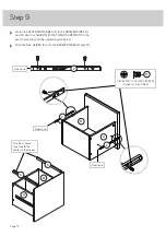
Page 14: ...HEAD SCREWS 11 in the exact holes shown in the upper diagram below å Push the FILE GLIDES 3 onto the DRAWER SIDES H and M Step 9 Page 14 Open end M H Open end M H 3 2 3 2 2 Open end SILVER 3 8 FLAT HEAD SCREW 4 used for the SLIDES 11 The tabs should face toward the center of the drawer ...

Page 15: ...wer with the EXTENSION RAILS on the unit and push the drawer into the unit until the drawer is fully inserted The drawer will push in hard until it is all the way in then it will slide in and out easier å Hang your letter files on the FILE GLIDES 3 as shown å NOTE Please read the back pages of the instruction booklet for important safety information å This completes assembly Clean with a damp cloth...

Page 16: ...rloaded drawers or shelves can break Never exceed the weight limits shown in the instructions Work from bottom to top when loading shelves and drawers Place the heavier items on the lower shelves or in lower drawers Placing TVs on furniture items that are not designed to support a television is hazardous Risk of injury or death TVs can be very heavy Plus the weight and location of the picture tube...

Reviews: