å
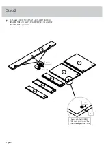
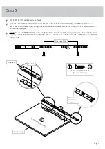
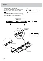
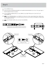
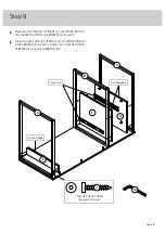
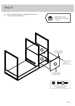
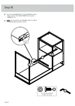
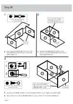
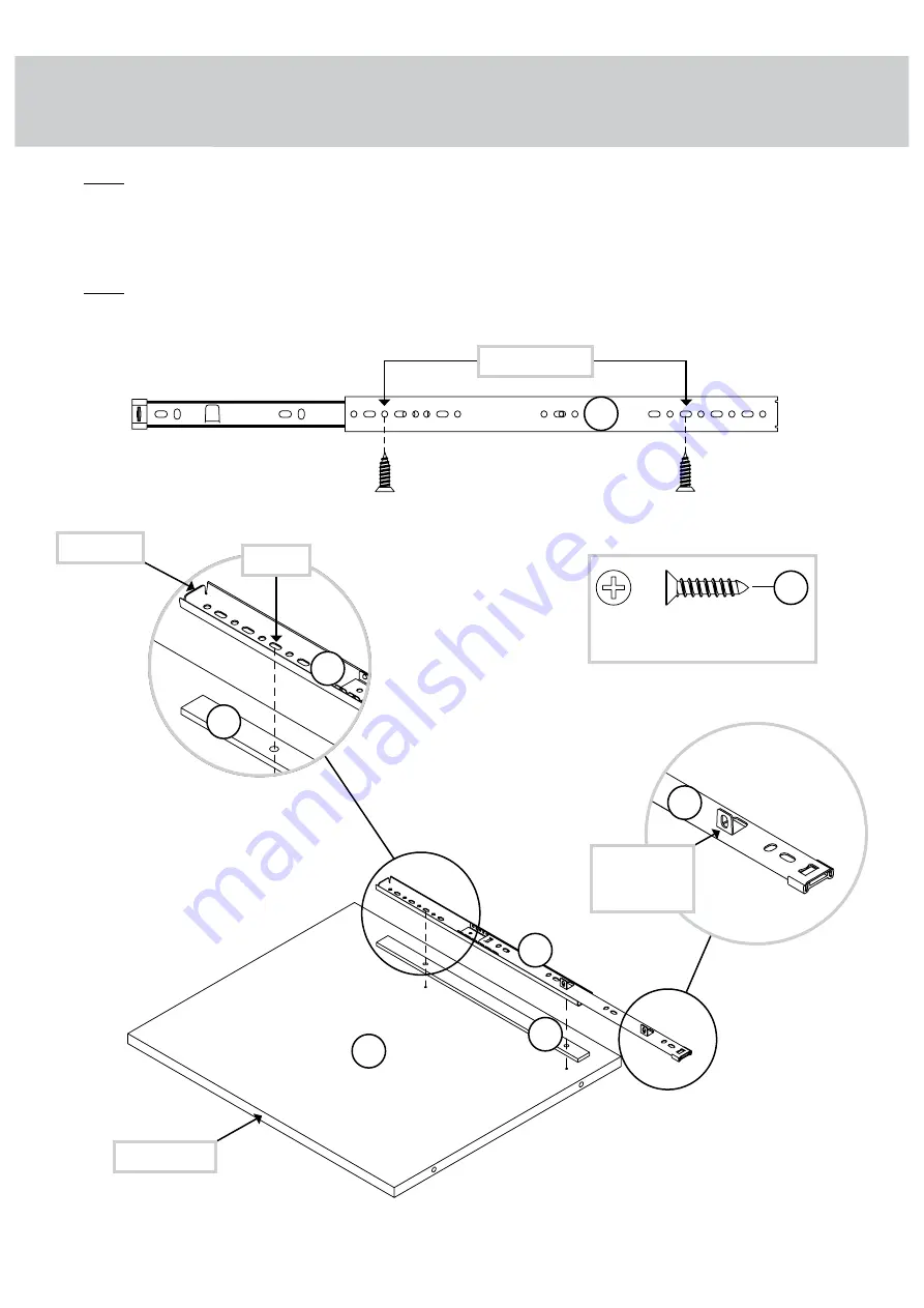
NOTE: Position the parts exactly as shown.
å
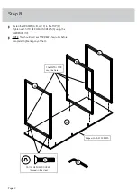
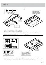
Fasten the RIGHT EXTENSION RAIL and SLIDE (16) to the EXTENSION BLOCK (M) and UPRIGHT (F). Use two
3/4" FLAT HEAD SCREWS (10) through the RIGHT EXTENSION RAIL and SLIDE, through the EXTENSION BLOCK,
and into the UPRIGHT.
å
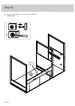
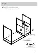
NOTE: For each EXTENSION RAIL, turn a SCREW into the hole shown in the enlarged diagram. Then, slide the inner
cartridge of the EXTENSION RAIL in to find the other hole that lines up with the hole in the UPRIGHT. Turn a SCREW
into this hole.
Step 3
Page 7
F
Finished edge
Surface with f
ewer ho
les
3/4" FLAT HEAD SCREW
(2 used in this step)
16
M
Closed end
Finished sur
face
6th hole
16
M
Bracket must
be positioned
as shown
16
Use these holes
16
10


