background image

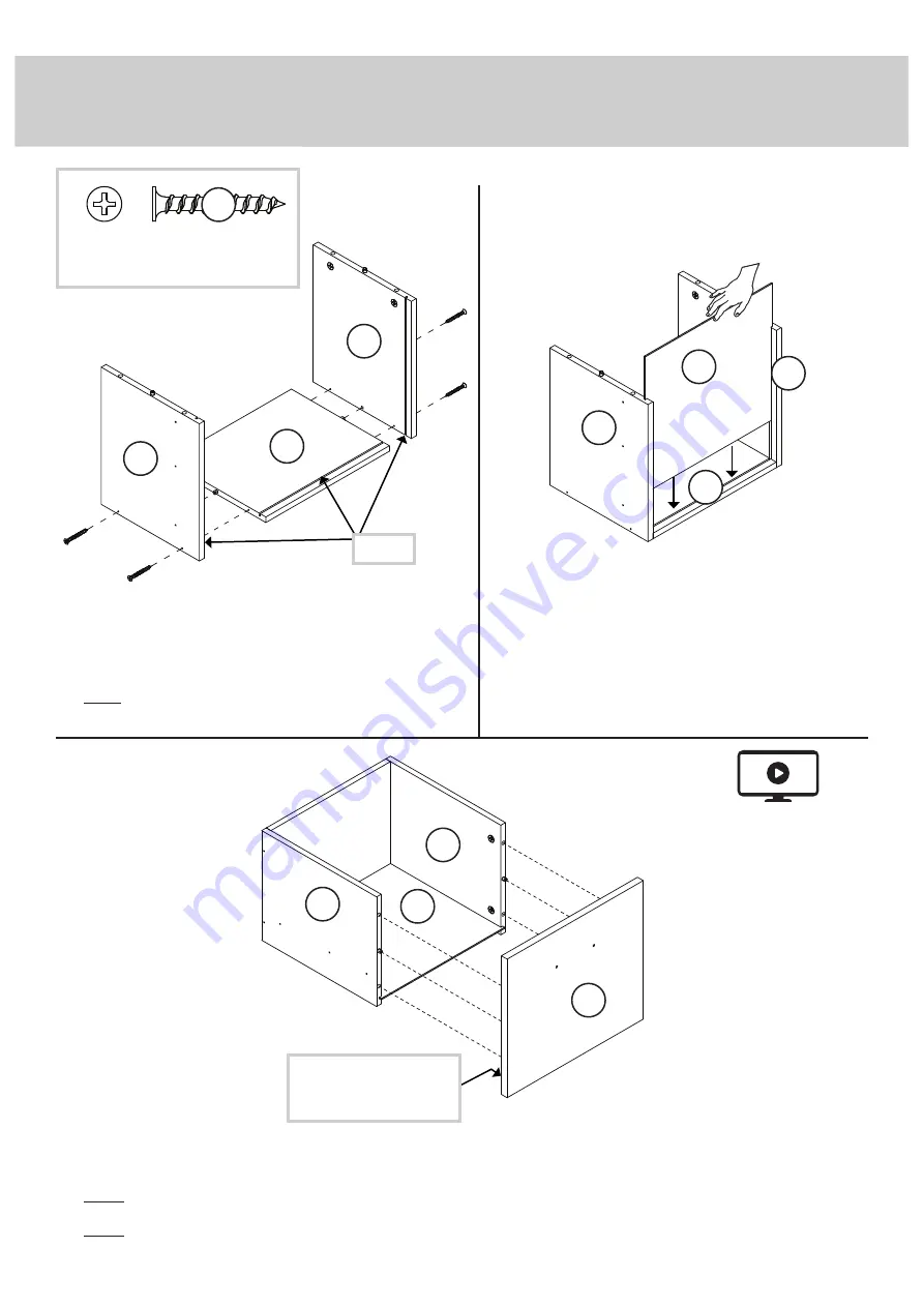
Step 12

 å

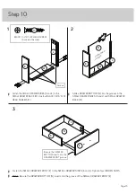
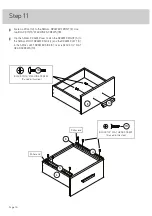
Fasten the LARGE DRAWER FRONT (F) to the LARGE DRAWER SIDES (G and H). Tighten four HIDDEN CAMS.

 å

NOTE: Be sure the DRAWER BOTTOM (N) inserts into the groove of the LARGE DRAWER FRONT (F).

 å

NOTE: Be sure the WOOD DOWELS in the LARGE DRAWER SIDES insert into the LARGE DRAWER FRONT.

1

2

3

 å

Fasten the LARGE DRAWER SIDES (G and H) to the
LARGE DRAWER BACK (J). Use four BLACK 1-3/16" FLAT 
HEAD SCREWS (17).

 å

NOTE: Be sure the WOOD DOWELS in the LARGE DRAWER
BACK inserts into the holes in the LARGE DRAWER SIDES.

 å

Slide a DRAWER BOTTOM (N) into the grooves in
the LARGE DRAWER SIDES (G and H) and LARGE 
DRAWER BACK (J). 

G

G

J

N

H

N

J

H

G

H

Unfi

 nished 

sur

face

Be sure the DRAWER 
BOTTOM inserts into the 
DRAWER FRONT groove.

Groove

F

BLACK 1-3/16" FLAT HEAD SCREW

(4 used in this step)

17

Page 17

Summary of Contents for Market 5425767

Page 1: ...Market L Shaped Desk Model 5425767 We re in your corner Teknik www teknikoffice co uk ...

Page 2: ...fication Assembly Steps Français Español Safety Warranty Hammer Not actual size No 2 Phillips Screwdriver Tip Shown Actual Size Skip the power trip This time Table of Contents Assembly Tools Required 3 4 5 20 21 24 25 28 29 30 31 Page 2 ...

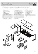
Page 3: ...EG 1 B LEFT UPRIGHT LEG 1 C BACK 1 D SHELF BOTTOM 2 E SMALL DRAWER FRONT 1 F LARGE DRAWER FRONT 1 G LARGE LEFT DRAWER SIDE 1 H LARGE RIGHT DRAWER SIDE 1 J LARGE DRAWER BACK 1 K SMALL LEFT DRAWER SIDE 1 L SMALL RIGHT DRAWER SIDE 1 M SMALL DRAWER BACK 1 N DRAWER BOTTOM 2 O SMALL TOP 1 P BRACE 1 Q WIRE SHELF 1 R FRONT LONG BRACE 1 S REAR LONG BRACE 1 T RIGHT END LEG 1 U REAR LEG 1 V LARGE TOP 1 W SHO...

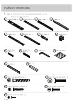
Page 4: ...9 10 CABINET RIGHT 1 5 DRAWER RIGHT 1 3 CABINET LEFT 1 6 DRAWER LEFT 1 4 EXTENSION SET SHOWN SEPARATED 1 EXTENSION RAIL 2 2 EXTENSION SLIDE 2 BLACK 1 3 16 FLAT HEAD SCREW 8 17 BLACK 1 7 8 HEX HEAD SCREW 4 15 BLACK 1 3 16 HEX HEAD SCREW 23 16 L WRENCH 1 11 FILE GLIDE 2 13 PULL 2 14 BLACK 1 2 FLAT HEAD SCREW 24 19 Page 4 18 BLACK 13 16 MACHINE SCREW 4 APPLIQUE CARD 1 12 ...

Page 5: ... Turn the CAM SCREW or gently tap the CAM DOWEL until the shoulder is against the surface of the part 1 3 1 2 Insert the CAM SCREW or CAM DOWEL into the HIDDEN CAM Tighten the HIDDEN CAM Hidden Cam Hidden Cam Arrow Push a HIDDEN CAM into the part The arrow in the HIDDEN CAM must point toward the hole in the edge of the board Hole 2 Page 5 ...

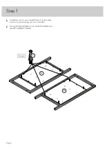
Page 6: ...tep 1 å Assemble your unit on a carpeted floor or on the empty carton to avoid scratching your unit or the floor å Turn eight CAM SCREWS 7 into the LEFT END LEG A and LEFT UPRIGHT LEG B 8 used 7 A B Page 6 ...

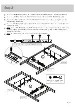
Page 7: ... END LEG A and LEFT UPRIGHT LEG B Use six BLACK 1 2 FLAT HEAD SCREWS 19 å NOTE For each EXTENSION RAIL turn a SCREW into the hole shown in the enlarged diagram Then slide the inner cartridge of the EXTENSION RAIL in to find the other holes that line up with the holes in the LEFT LEGS Turn a SCREW into those holes å NOTE The EXTENSION SLIDES will be used later for the LARGE DRAWER Step 2 A B Open en...

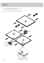
Page 8: ...nto the edges of the BACK C and SHELF BOTTOMS D å Push eight HIDDEN CAMS 8 into the SHELF BOTTOMS D Step 3 C D D 10 10 8 Arrow Arrow 8 Arrow The arrow in the HIDDEN CAM must point toward the hole in the edge of the board Hole 8 used Page 8 ...

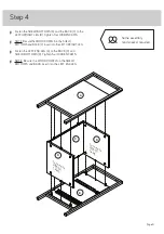
Page 9: ...F BOTTOMS and BACK C insert into the LEFT UPRIGHT LEG å Fasten the LEFT END LEG A to the BACK C and SHELF BOTTOMS D Tighten four HIDDEN CAMS å NOTE Be sure the WOOD DOWELS in the SHELF BOTTOMS and BACK insert into the LEFT END LEG Step 4 A B C D D Surface with HIDDEN CAMS Surface with HIDDEN CAMS Page 9 Some assembly and snacks required ...

Page 10: ... using the L WRENCH 11 å Fasten the LONG BRACES R and S to the LEGS T and U Tighten four BLACK 1 3 16 HEX HEAD SCREWS 16 using the L WRENCH 11 Step 5 The wire grate and metal frame should be even BLACK 1 3 16 HEX HEAD SCREW 8 used in this step 16 T U These holes must be here Q R S 11 Page 10 ...

Page 11: ... the L WRENCH 11 å Fasten the LEFT UPRIGHT LEG B to the BRACE P Tighten two BLACK 1 7 8 HEX HEAD SCREWS 15 using the L WRENCH 11 å Fasten the SHORT BRACE W to the FRONT LONG BRACE R and LEFT UPRIGHT LEG B Tighten two BLACK 1 3 16 HEX HEAD SCREWS 16 using the L WRENCH 11 BLACK 1 3 16 HEX HEAD SCREW 2 used in this step 16 Step 6 P W P Arrow 8 10 Surface with HIDDEN CAM BLACK 1 7 8 HEX HEAD SCREW 4 u...

Page 12: ...o the LONG BRACES R and S and LEGS T and U Tighten eight BLACK 1 3 16 HEX HEAD SCREWS 16 using the L WRENCH 11 Step 7 R S T U S u r f a c e w i t h o u t h o l e s V 11 BLACK 1 3 16 HEX HEAD SCREW 8 used in this step 16 Page 12 ...

Page 13: ... HIDDEN CAM in the BRACE Tighten five BLACK 1 3 16 HEX HEAD SCREWS 16 using the L WRENCH 11 å NOTE Be sure the WOOD DOWEL in the BRACE inserts into the SMALL TOP Step 8 O O FLIP O V E R S u r f a c e w i t h o u t h o l e s 11 BLACK 1 3 16 HEX HEAD SCREW 5 used in this step 16 A B P W Page 13 Side Step Make nachos Optional but recommended 7 ...

Page 14: ... 8 8 used å Turn eight CAM SCREWS 7 into the DRAWER FRONTS E and F å Insert four SMALL WOOD DOWELS 9 into the edges of the LARGE DRAWER SIDE G and H and LARGE DRAWER BACK J å Push eight HIDDEN CAMS 8 into the DRAWER SIDES G H K and L Page 14 ...

Page 15: ...E 1 2 3 å Fasten the SMALL DRAWER SIDES K and L to the SMALL DRAWER BACK M Use four BLACK 1 3 16 FLAT HEAD SCREWS 17 å Slide a DRAWER BOTTOM N into the grooves in the SMALL DRAWER SIDES K and L and SMALL DRAWER BACK M K K L N L N M M K L Be sure the DRAWER BOTTOM inserts into the DRAWER FRONT groove Groove E BLACK 1 3 16 FLAT HEAD SCREW 4 used in this step 17 Unfinished surface Page 15 ...

Page 16: ...ER over Fasten the DRAWER RIGHT 3 to the SMALL RIGHT DRAWER SIDE L and the DRAWER LEFT 4 to the SMALL LEFT DRAWER SIDE K Use six BLACK 1 2 FLAT HEAD SCREWS 19 Step 11 E L K Roller end Roller end 14 3 4 BLACK 1 2 FLAT HEAD SCREW 6 used in this step 19 Page 16 BLACK 13 16 MACHINE SCREW 2 used in this step 18 ...

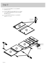
Page 17: ...3 å Fasten the LARGE DRAWER SIDES G and H to the LARGE DRAWER BACK J Use four BLACK 1 3 16 FLAT HEAD SCREWS 17 å NOTE Be sure the WOOD DOWELS in the LARGE DRAWER BACK inserts into the holes in the LARGE DRAWER SIDES å Slide a DRAWER BOTTOM N into the grooves in the LARGE DRAWER SIDES G and H and LARGE DRAWER BACK J G G J N H N J H G H Unfinished surface Be sure the DRAWER BOTTOM inserts into the DR...

Page 18: ...CK 13 16 MACHINE SCREWS 18 å Fasten the EXTENSION SLIDES 2 to the LARGE DRAWER SIDES G and H Use six BLACK 1 2 FLAT HEAD SCREWS 19 BLACK 1 2 FLAT HEAD SCREW 6 used in this step 19 2 2 14 F G H Open end Open end Page 18 BLACK 13 16 MACHINE SCREW 2 used in this step 18 ...

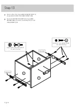
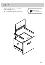
Page 19: ...Push two FILE GLIDES 13 onto the top edges of the LARGE DRAWER SIDES G and H å NOTE This drawer is designed to hold letter size hangers Step 14 G H 13 13 Letter Page 19 Almost time to celebrate With a nap ...

Page 20: ...t and push the drawer into the unit until the drawer is fully inserted The drawer will push in hard until it is all the way in then it will slide in and out easier å Peel APPLIQUES from the APPLIQUE CARD 12 and stick them onto each visible HIDDEN CAM å NOTE Please read the back pages of the instruction booklet for important safety information å This completes assembly Clean with a damp cloth Wipe ...

Page 21: ...y moving furniture that is not designed and equipped with casters Furniture can tip over or break if improperly moved Physical injury Furniture can be very heavy Breakage of tops particularly with double pedestal furniture drawers at both ends Unload shelves and drawers from top to bottom before moving the unit Do not push furniture especially on a carpeted floor Have a friend help you lift the ite...

Reviews: