å
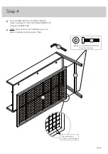
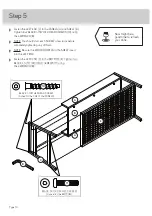
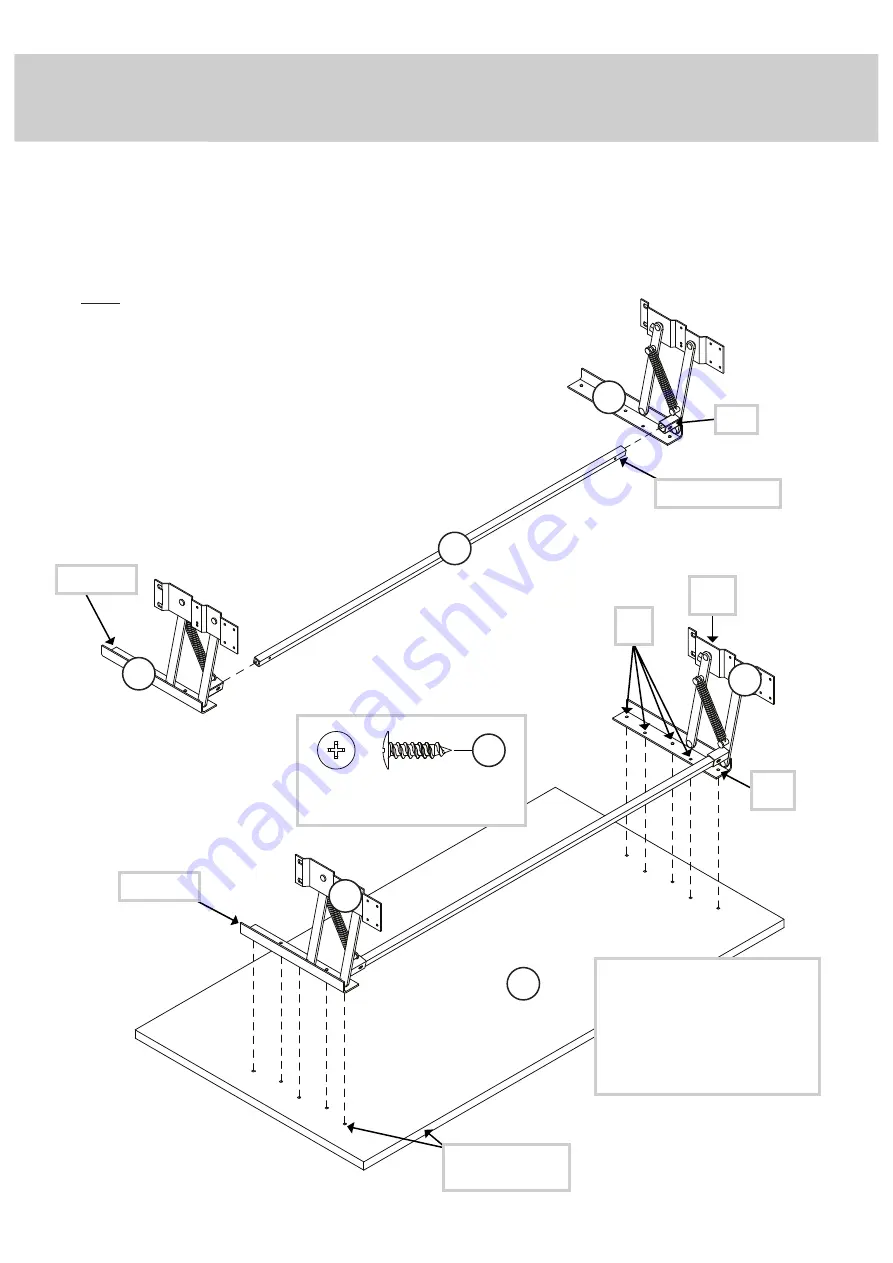
Insert the ends of the STRETCHER (7) into the posts on the LIFT
TABLE MECHANISM SET (9). Be sure the holes in the STRETCHER
line up with the holes in the posts.
å
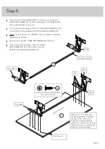
First, fasten the front edges of the LIFT TABLE MECHANISM SET (9)
to the TOP (F). Use eight BLACK 9/16" PAN HEAD SCREWS (13).
å
NOTE: You should start each SCREW a few turns before completely
tightening any of them.
å
Second, press the LIFT TABLE MECHANISM SET (9) down.
å
Third, fasten the back edges of the LIFT TABLE
MECHANISM SET (9) to the TOP (F). Use two
BLACK 9/16" PAN HEAD SCREWS (13).
Step 6
Page 11
F
Meet Part (F). This component
has been engineered to be lighter,
stronger, faster… well ok. Not
technically faster. But defi nitely
makes for a sturdier Lift-Top Coff ee
Table that’s easier to assemble and
friendlier to the environment.
7
9
9
Surface with holes
The holes are
Front edge
2
nd
3
rd
1
st
Sur
face with holes
Post
9
9
Front edge
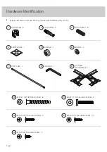
BLACK 9/16" PAN HEAD SCREW
(10 used in this step)
13

