background image

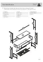
Part Identifi cation

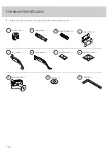
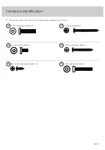
Hardware Identifi cation

Assembly Steps

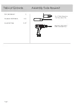
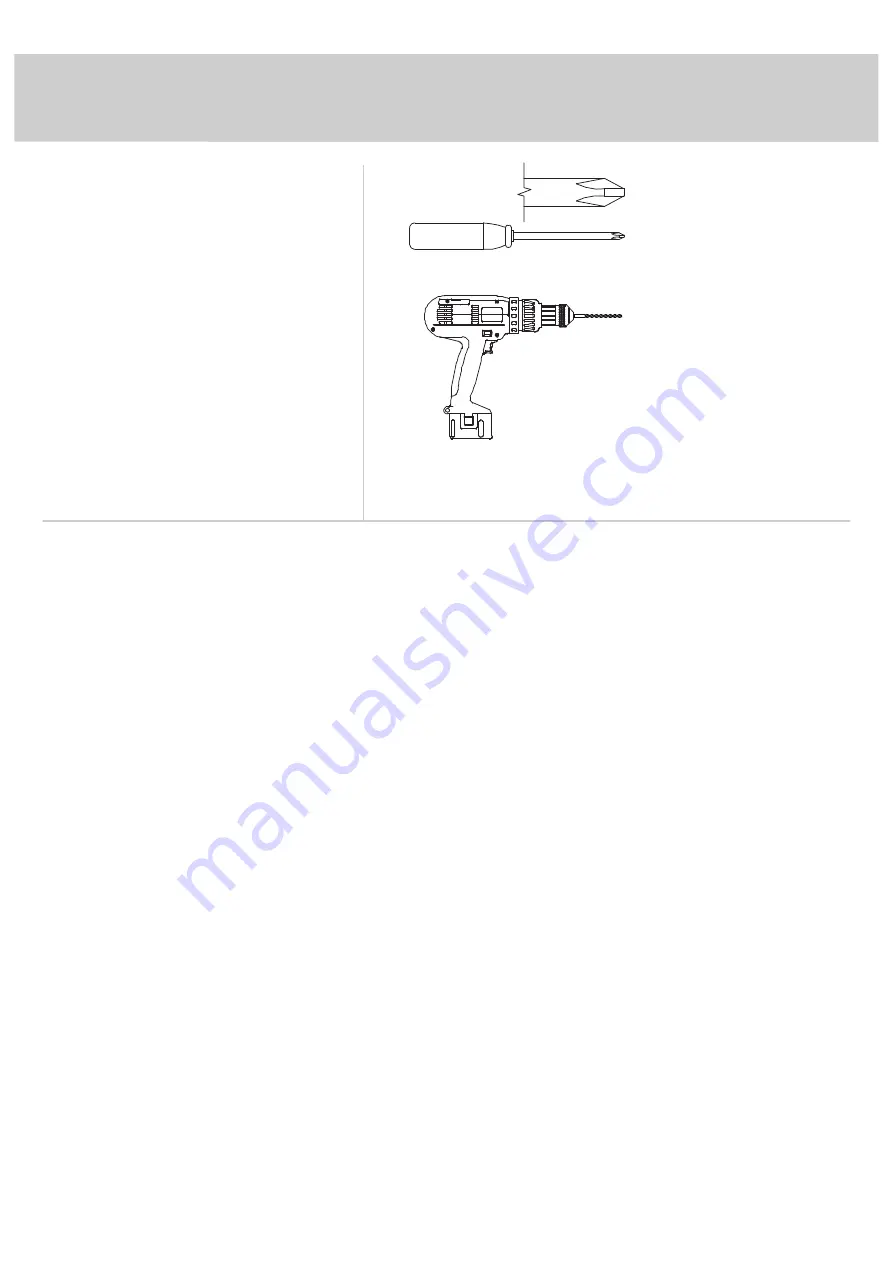
No. 2 Phillips Screwdriver
Tip Shown Actual Size

Table of Contents

Assembly Tools Required

3

4-5

6-21

Page 2

Electric drill with 5/16" bit
(ONLY in indicated step)

Summary of Contents for New Hyde 426440

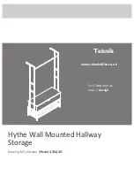
Page 1: ...Hythe Wall Mounted Hallway Storage New Hyde Collection Model 426440 You ll love what we have in storage Teknik www teknikoffice co uk ...

Page 2: ...entification Hardware Identification Assembly Steps No 2 Phillips Screwdriver Tip Shown Actual Size Table of Contents Assembly Tools Required 3 4 5 6 21 Page 2 Electric drill with 5 16 bit ONLY in indicated step ...

Page 3: ... to help distinguish similar parts from each other Use this part identification to help identify similar parts Now you know our ABCs A FRONT 1 B LEFT END 1 C RIGHT END 1 D BACK 1 E BOTTOM 1 F TOP 1 G LEFT LEG 1 H RIGHT LEG 1 J BRACE 2 K RACK 1 L LOWER FRAME 2 M UPPER FRAME 2 N ROD 1 A B C D E F G H J J K L L M M N Page 3 ...

Page 4: ...shown actual size You may receive extra hardware with your unit CAM SCREW 4 2 HIDDEN CAM 4 1 WOOD DOWEL 12 3 REAR HINGE 3 4 LEFT HINGE 1 5 RIGHT HINGE 1 6 7 BUMPER CARD 1 APPLIQUE CARD 1 8 WALL ANCHOR 2 9 WASHER 4 10 L WRENCH 1 11 Page 4 ...

Page 5: ...are shown actual size You may receive extra hardware with your unit 1 2 HEX HEAD SCREW 8 14 1 9 16 PAN HEAD SCREW 12 15 1 3 16 HEX HEAD SCREW 18 12 2 PAN HEAD SCREW 2 13 Page 5 BLACK 9 16 PAN HEAD SCREW 23 16 1 3 8 HEX HEAD SCREW 4 17 ...

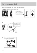
Page 6: ... Turn the CAM SCREW or gently tap the CAM DOWEL until the shoulder is against the surface of the part 1 Hidden Cam Hidden Cam Arrow Push a HIDDEN CAM into the part The arrow in the HIDDEN CAM must point toward the hole in the edge of the board Hole 2 3 1 2 Insert the CAM SCREW or CAM DOWEL into the HIDDEN CAM Tighten the HIDDEN CAM Page 6 ...

Page 7: ...r or on the empty carton to avoid scratching your unit or the floor å Turn four CAM SCREWS 2 into the FRONT A å Push four HIDDEN CAMS 1 into the ENDS B and C A B C 2 Arrow 1 Page 7 Just think The sooner you do this the sooner you do something else ...

Page 8: ...sert two WOOD DOWELS 3 into the FRONT A å Fasten the ENDS B and C to FRONT A Tighten four HIDDEN CAMS å NOTE Be sure the WOOD DOWELS in the FRONT insert into the ENDS Step 2 A B C Notch Finished edge 3 3 Page 8 ...

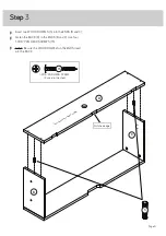
Page 9: ...Fasten the BACK D to the ENDS B and C Use four 1 9 16 PAN HEAD SCREWS 15 å NOTE Be sure the WOOD DOWELS in the ENDS insert into the BACK Step 3 B C D 3 1 9 16 PAN HEAD SCREW 4 used in this step 15 S u r f a c e w i t h f e w e r h o l e s Notched edge Page 9 ...

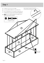
Page 10: ... å Fasten the BOTTOM E to the FRONT A ENDS B and C and BACK D Use eight 1 9 16 PAN HEAD SCREWS 15 å NOTE Be sure the WOOD DOWELS in the SHELF insert into the FRONT ENDS and BACK Step 4 B C D A E 3 8 used These holes are further from this edge 1 9 16 PAN HEAD SCREW 8 used in this step 15 Page 10 ...

Page 11: ...Step å Carefully turn your unit onto the BACK D å Fasten the REAR HINGES 4 to the BACK D Use nine BLACK 9 16 PAN HEAD SCREWS 16 Step 5 D 4 9 16 PAN HEAD SCREW 9 used in this step 16 Page 11 ...

Page 12: ...Step å Fasten the TOP F to the BACK D Use six 9 16 PAN HEAD SCREWS 16 Step 6 D F 9 16 PAN HEAD SCREW 6 used in this step 16 Page 12 ...

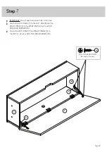
Page 13: ...n the LEFT HINGE 5 to the LEFT END B and the RIGHT HINGE 6 to the RIGHT END C Use four 9 16 PAN HEAD SCREWS 16 å Fasten the LEFT HINGE 5 and RIGHT HINGE 6 to the TOP F Use four 9 16 PAN HEAD SCREWS 16 Step 7 F B C 9 16 PAN HEAD SCREW 8 used in this step 16 Page 13 5 6 ...

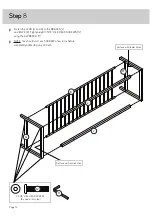
Page 14: ...n eight 1 3 16 HEX HEAD SCREWS 12 using the L WRENCH 11 å NOTE You should start each SCREW a few turns before completely tightening any of them Step 8 G H K J J 11 1 3 16 HEX HEAD SCREW 8 used in this step 12 Surface with more holes Surface with fewer holes Page 14 ...

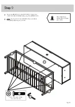
Page 15: ... 1 3 16 HEX HEAD SCREWS 12 using the L WRENCH 11 å NOTE You should start each SCREW a few turns before completely tightening any of them Step 9 E J J 11 1 3 16 HEX HEAD SCREW 4 used in this step 12 Page 15 Now might be a good time to refresh your drink G H ...

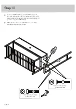
Page 16: ... 3 16 HEX HEAD SCREWS 12 and two 1 3 8 HEX HEAD SCREW 17 as shown using the L WRENCH 11 å NOTE You should start each SCREW a few turns before completely tightening any of them Step 10 B L 11 1 3 16 HEX HEAD SCREW 2 used in this step 12 10 G Page 16 1 3 8 HEX HEAD SCREW 2 used in this step 17 ...

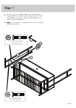
Page 17: ...n two 1 3 16 HEX HEAD SCREWS 12 and two 1 3 8 HEX HEAD SCREW 17 as shown using the L WRENCH 11 å NOTE You should start each SCREW a few turns before completely tightening any of them Step 11 C H L 11 10 Page 17 1 3 8 HEX HEAD SCREW 2 used in this step 17 1 3 16 HEX HEAD SCREW 2 used in this step 12 ...

Page 18: ...UPPER FRAMES M Tighten two 1 3 16 HEX HEAD SCREWS 12 using the L WRENCH 11 å NOTE You should start each SCREW a few turns before completely tightening any of them Step 12 M M N 11 1 3 16 HEX HEAD SCREW 2 used in this step 12 Page 18 ...

Page 19: ...t 1 2 HEX HEAD SCREWS 14 using the L WRENCH 11 å NOTE You should start each SCREW a few turns before completely tightening any of them Step 13 L M M L 11 Page 19 If you re doing this to help a friend don t leave without a bite 1 2 HEX HEAD SCREW 8 used in this step 14 ...

Page 20: ...e even with the surface of the wall å Stand your unit upright placing the brackets in the UPPER FRAMES M over the WALL ANCHORS 9 å Turn two 2 PAN HEAD SCREWS 15 through the holes in the UPPER FRAMES M and into the WALL ANCHORS 9 å NOTE You will need to turn the 2 PAN HEAD SCREWS 13 multiple turns to completely tighten and secure your unit to the wall Step 14 M M Page 20 2 PAN HEAD SCREW 2 used in ...

Page 21: ...7 and stick them onto the top edges of the ENDS B and C where the TOP F comes into contact with the ENDS å NOTE Please read the back pages of the instruction booklet for important safety information å This completes assembly Clean with a damp cloth Wipe dry Step 15 8 To cover HIDDEN CAMS 7 B C F N 40 lbs 3 5 l b s 3 5 l b s Page 21 ...

Page 22: ...sult in death or serious injury due to furniture collapse or tip over NEVER place a TV on furniture that is not intended to support a TV This product is not designed to support a television unless a TV warning label is included and the instructions specifically state the size and weight of the television Overloading drawers and shelves may result in furniture that can break or sag or tip over which...

Reviews: