background image

Hardware Identifi cation


å

Screws are shown actual size. You may receive extra hardware with your unit.

Page 4

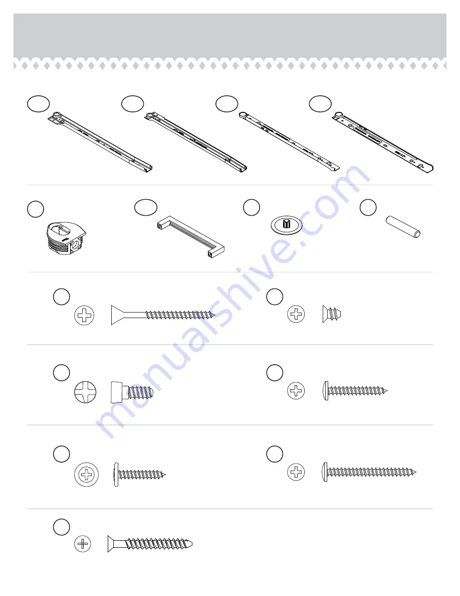
35DA

CABINET RIGHT - 1

35DB

CABINET LEFT - 1

35DC

DRAWER RIGHT - 1

35DD

DRAWER LEFT - 1

HIDDEN 
CONNECTOR - 8

5F

PULL - 1

104K

SCREW COVER - 8

20P

METAL PIN - 8

1R

CONNECTOR SCREW - 8

8S

BLACK 7/8" LARGE HEAD SCREW - 2

17S

BLACK 1-7/8" FLAT HEAD SCREW - 16

2S

3S

GOLD 5/16" FLAT HEAD SCREW - 8

BLACK 1-5/8" PAN HEAD SCREW - 2

27S

BLACK 1-1/8" PAN HEAD SCREW - 8

9S

30S

BLACK 1-9/16" FLAT HEAD SCREW - 4

Summary of Contents for Trestle 5410421

Page 1: ...TION BOOKLET CONTAINS IMPORTANT SAFETY INFORMATION PLEASE READ AND KEEP FOR FUTURE REFERENCE Trestle Desk 5410421 Cinnamon Cherry 5417061 Soft White You could totally write a novel on this Teknik www teknikoffice co uk ...

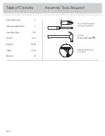
Page 2: ...equired 3 4 5 14 15 17 18 20 21 22 23 Part Identification Hardware Identification Assembly Steps Français Español Safety Warranty Hammer Not actual size No 2 Phillips Screwdriver Tip Shown Actual Size Skip the power trip This time Page 2 ...

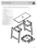
Page 3: ...ation to help identify similar parts A END 2 B RIGHT UPRIGHT 1 C LEFT UPRIGHT 1 D TOP 1 E BACK 1 F FRONT 2 G STRETCHER 2 H RIGHT FRONT LEFT REAR LEG 2 I LEFT FRONT RIGHT REAR LEG 2 J DRAWER FRONT 1 D266 RIGHT DRAWER SIDE 1 D267 LEFT DRAWER SIDE 1 D268 DRAWER BACK 1 D269 DRAWER BOX FRONT 1 D622 DRAWER BOTTOM 1 Now you know our ABCs Page 3 A A B C D E F F G G H H I I J D266 D268 D267 D269 D622 ...

Page 4: ...BINET LEFT 1 35DC DRAWER RIGHT 1 35DD DRAWER LEFT 1 HIDDEN CONNECTOR 8 5F PULL 1 104K SCREW COVER 8 20P METAL PIN 8 1R CONNECTOR SCREW 8 8S BLACK 7 8 LARGE HEAD SCREW 2 17S BLACK 1 7 8 FLAT HEAD SCREW 16 2S 3S GOLD 5 16 FLAT HEAD SCREW 8 BLACK 1 5 8 PAN HEAD SCREW 2 27S BLACK 1 1 8 PAN HEAD SCREW 8 9S 30S BLACK 1 9 16 FLAT HEAD SCREW 4 ...

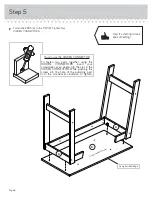
Page 5: ...ur unit on a carpeted floor or on the empty carton to avoid scratching your unit or the floor å Use your hammer to tap two HIDDEN CONNECTORS 5F with SCREWS into one of the ENDS A å Repeat this step for the other END A RIGHT UPRIGHT B and LEFT UPRIGHT C Step 2 8S 5F A 5F 8 used Page 5 ...

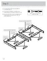
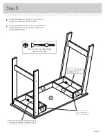
Page 6: ...d I å Now fasten the LEGS H and I to the ENDS A and STRETCHERS G Use eight BLACK 1 7 8 FLAT HEAD SCREWS 2S Page 6 1R 1R 1R 1R A A G G H H I I Surface with HIDDEN CONNECTOR These edges should be even These edges should be even These edges should be even These edges should be even Surface with HIDDEN CONNECTOR BLACK 1 7 8 FLAT HEAD SCREW 8 used in this step 2S ...

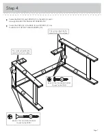
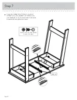
Page 7: ...S A to the BACK E and FRONTS F Use four BLACK 1 7 8 FLAT HEAD SCREWS 2S Step 4 Page 7 A E F F H H I I This surface should be the same finish as this surface This surface should be the same finish as this surface A BLACK 1 7 8 FLAT HEAD SCREW 4 used for the ENDS 2S BLACK 1 1 8 PAN HEAD SCREW 8 used for the LEGS 9S ...

Page 8: ...TOR To fasten two parts together using the HIDDEN CONNECTORS insert your screwdriver at an angle into the slot in the HIDDEN CONNECTOR While pushing the screw into the hole of the adjoining part turn the screwdriver clockwise to tighten Long finished edge Unfinished surface Hey It s starting to look like something ...

Page 9: ...N CONNECTORS å Fasten the UPRIGHTS B and C to the BACK E and FRONTS F Use four BLACK 1 7 8 FLAT HEAD SCREWS 2S Step 6 Page 9 B D E F F C Surface with HIDDEN CONNECTORS Finished edge Surface with HIDDEN CONNECTORS BLACK 1 7 8 FLAT HEAD SCREW 4 used in this step 2S ...

Page 10: ...DA to the RIGHT UPRIGHT B and the CABINET LEFT 35DB to the LEFT UPRIGHT C Use four GOLD 5 16 FLAT HEAD SCREWS 3S through holes 1 and 3 Page 10 1 1 2 2 3 3 B C 35DB 35DB Roller end 35DA 35DA GOLD 5 16 FLAT HEAD SCREW 4 used in this step 3S ...

Page 11: ...LACK 1 9 16 FLAT HEAD SCREWS 30S å Slide the DRAWER BOTTOM D622 into the grooves in the DRAWER SIDES D266 and D267 and DRAWER BACK D268 Step 8 Page 11 Groove F i n i s h e d s u r f a c e D266 D268 D267 D622 D266 D268 D267 BLACK 1 9 16 FLAT HEAD SCREW 2 used in this step 30S ...

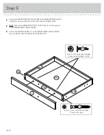
Page 12: ...Be sure the DRAWER BOTTOM D622 inserts into the groove of the DRAWER BOX FRONT D269 å Fasten the DRAWER FRONT J to the DRAWER BOX FRONT D269 Use two BLACK 7 8 LARGE HEAD SCREWS 17S Page 12 J D266 D269 D267 D622 BLACK 1 9 16 FLAT HEAD SCREW 2 used in this step 30S 30S BLACK 7 8 LARGE HEAD SCREW 2 used for the DRAWER FRONT 17S ...

Page 13: ...L 104K to the DRAWER FRONT J Use two BLACK 1 5 8 PAN HEAD SCREWS 27S through the DRAWER BOX FRONT through the DRAWER FRONT and into the PULL Step 10 Page 13 J 1 2 3 1 2 3 35DC 35DC 35DD 35DD D266 D267 104K Roller end Roller end BLACK 1 5 8 PAN HEAD SCREW 2 used for the PULL 27S GOLD 5 16 FLAT HEAD SCREW 4 used for the SLIDES 3S Almost time to celebrate With a nap ...

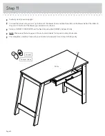
Page 14: ...unit Lift the front of the drawer up and slide it into the unit å Center a SCREW COVER 20P over the head of each visible SCREW and press firmly å NOTE Please read the back pages of the instruction booklet for important safety information å This completes assembly Clean with your favorite furniture polish or a damp cloth Wipe dry Page 14 20P 5 lbs 40 lbs 8 used To cover screws ...

Page 15: ...y moving furniture that is not designed and equipped with casters Furniture can tip over or break if improperly moved Physical injury Furniture can be very heavy Breakage of tops particularly with double pedestal furniture drawers at both ends Unload shelves and drawers from top to bottom before moving the unit Do not push furniture especially on a carpeted floor Have a friend help you lift the ite...

Reviews: