background image

www.teknikoffice.co.uk

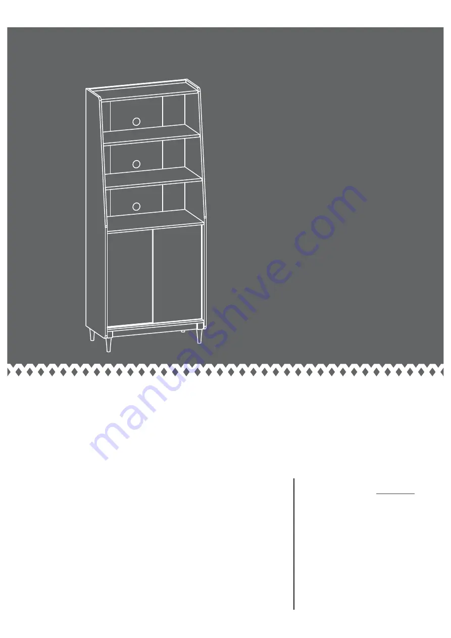
Wide Bookcase

Hampstead Park Collection | 

Model


5420282

NOTE: 

THIS INSTRUCTION 

BOOKLET CONTAINS 

IMPORTANT


SAFETY INFORMATION.

PLEASE READ AND KEEP FOR 
FUTURE REFERENCE. 

The 

stories

 of your 

life

.

Teknik

Summary of Contents for Wide Bookcase 5420282

Page 1: ...ikoffice co uk Wide Bookcase Hampstead Park Collection Model 5420282 NOTE THIS INSTRUCTION BOOKLET CONTAINS IMPORTANT SAFETY INFORMATION PLEASE READ AND KEEP FOR FUTURE REFERENCE The stories of your life Teknik ...

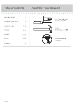
Page 2: ...equired 3 4 5 18 19 21 22 24 25 26 27 Part Identification Hardware Identification Assembly Steps Français Español Safety Warranty Hammer Not actual size No 2 Phillips Screwdriver Tip Shown Actual Size Skip the power trip This time Page 2 ...

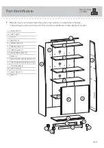
Page 3: ...er Use this part identification to help identify similar parts A RIGHT END 1 B LEFT END 1 C TOP 1 D BOTTOM 1 E UPPER SHELF 1 F MIDDLE SHELF 1 G LOWER SHELF 1 H ADJUSTABLE SHELF 1 I SKIRT 2 J RIGHT FRONT LEFT REAR FOOT 2 K LEFT FRONT RIGHT REAR FOOT 2 L TOP MOLDING 1 M LEFT DOOR 1 N RIGHT DOOR 1 O BACK 1 Now you know our ABCs Page 3 A B C D E F G H I J K L M N O I J K ...

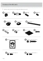
Page 4: ... 32 1 CAM SCREW 32 2 SHORT WOOD DOWEL 4 4 LONG WOOD DOWEL 32 3 APPLIQUE CARD 1 10 BLACK 1 2 FLAT HEAD SCREW 16 14 BLACK 1 2 PAN HEAD SCREW 8 13 FURNITURE TIPPING RESTRAINT KIT 1 99 12 BLACK 1 1 4 FLAT HEAD SCREW 4 DOOR HANDLE 2 7 METAL PIN 4 8 RUBBER SLEEVE 4 9 NAIL 53 11 LOWER GUIDE 4 6 UPPER GUIDE 4 5 Page 4 ...

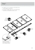
Page 5: ...tching your unit or the floor å Push thirty two HIDDEN CAMS 1 into the TOP C BOTTOM D SHELVES E F and G SKIRTS I and FEET J and K Arrow The arrow in the HIDDEN CAM must point toward the hole in the edge of the board Hole 1 Arrow 32 used Arrow 1 1 Arrow Arrow 1 Page 5 C D E F G I I K J ...

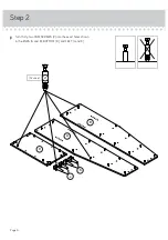
Page 6: ...Step 2 å Turn thirty two CAM SCREWS 2 into the exact holes shown in the ENDS A and B BOTTOM D and FEET J and K Page 6 2 32 used A D B K J ...

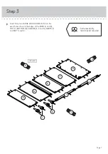
Page 7: ...o LARGE WOOD DOWELS 3 into the exact holes shown in the edges of the ENDS A and B TOP C BOTTOM D SHELVES E F and G SKIRTS I and FEET J and K Step 3 Page 7 3 3 32 used C D E F G I I Some assembly and snacks required 3 K J ...

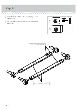
Page 8: ... 4 å Fasten the SKIRTS I to the FEET J and K Tighten four HIDDEN CAMS å NOTE Be sure the WOOD DOWELS in the SKIRTS insert into the FEET Page 8 1 2 I J K I J K Edge with WOOD DOWELS Surface with HIDDEN CAMS ...

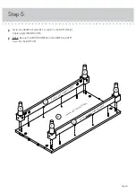
Page 9: ... to the BOTTOM D Tighten eight HIDDEN CAMS å NOTE Be sure the WOOD DOWELS in the SKIRTS and FEET insert into the BOTTOM Step 5 Page 9 D I K J K J Surface with HIDDEN CAMS I Surface without HIDDEN CAMS S u r f a c e w i t h C A M S C R E W S ...

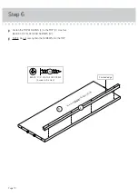
Page 10: ... L to the TOP C Use four BLACK 1 1 4 FLAT HEAD SCREWS 12 å NOTE Do not over tighten the SCREWS into the TOP Page 10 BLACK 1 1 4 FLAT HEAD SCREW 4 used in this step 12 C L S u r f a c e w i t h o u t H I D D E N C A M S Finished edge ...

Page 11: ... HIDDEN CAMS å NOTE Be sure the WOOD DOWELS in the TOP BOTTOM SHELVES and FEET insert into the LEFT END Step 7 Page 11 B D G K J 4 If you re doing this to help a friend don t leave without a bite Surface with HIDDEN CAMS F Surface with HIDDEN CAMS E Surface with HIDDEN CAMS C Surface with HIDDEN CAMS Rounded edge Finished edge Groove ...

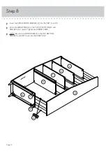
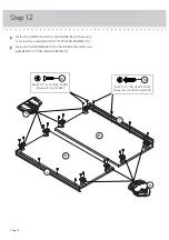
Page 12: ...OOD DOWELS 4 into the FEET J and K å Fasten the RIGHT END A to the TOP C BOTTOM D and SHELVES E F and G Tighten ten HIDDEN CAMS å NOTE Be sure the WOOD DOWELS in the TOP BOTTOM SHELVES and FEET insert into the RIGHT END A C D E F G K J 4 ...

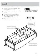
Page 13: ...nto the holes that line up over the SHELVES E F and G å NOTE Perforations have been provided for access through the BACK Carefully cut out the holes needed Step 9 Page 13 Do not stand the unit upright without the BACK fastened The unit may collapse Caution U n fi n i s h e d s u r f a c e NAIL 53 used in this step 11 This hole must be here for the FURNITURE TIPPING RESTRAINT KIT in the next step Th...

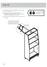
Page 14: ...n against a wall å We recommend using the FURNITURE TIPPING RESTRAINT KIT 99 for added stability Fasten a bracket to the TOP C using the 5 8 screw as shown å Follow the instructions included in the KIT to fasten your unit to the wall 99 Use the 5 8 screw through the small hole in a bracket and into the back edge of the TOP C Small hole C ...

Page 15: ...he METAL PINS into the hole locations of your choice in the ENDS A and B Set the ADJUSTABLE SHELF H onto the METAL PINS å Peel a sticker from the APPLIQUE CARD 10 and place onto each visible HIDDEN CAM Step 11 Page 15 www sauder com 420282 4 used 8 9 H A B 10 ...

Page 16: ...exactly as shown Use sixteen BLACK 1 2 FLAT HEAD SCREWS 14 å Fasten the DOOR HANDLES 7 to the DOORS M and N Use eight BLACK 1 2 PAN HEAD SCREWS 13 M 6 5 N 7 7 BLACK 1 2 FLAT HEAD SCREW 16 used for the GUIDES 14 BLACK 1 2 PAN HEAD SCREW 8 used for the DOOR HANDLES 13 ...

Page 17: ... tilt the LEFT DOOR M up vertically Push the UPPER GUIDE 5 tabs up into the rear track in the LOWER SHELF G å NOTE The DOOR should slide freely in the track å Repeat this step for the RIGHT DOOR N using the front tracks in the BOTTOM D and LOWER SHELF G Page 17 The tab should be down before you insert it into the upper track The tab should be up after the DOOR is in place D G M ...

Page 18: ... Please read the back pages of the instruction booklet for important safety information å This completes assembly Clean with your favorite furniture polish or a damp cloth Wipe dry 20 lbs 25 lbs 30 lbs 15 lbs no load 25 lbs ...

Page 19: ...er or break if improperly moved Physical injury Furniture can be very heavy Unload shelves from top to bottom before moving the furniture Do not push furniture especially on a carpeted floor Have a friend help you lift the item and set it in place This unit must be positioned against a wall Children climbing on the shelves can cause the product to tip Risk of injury or death Do not allow children t...

Reviews: