AVVERTENZE
1. I colori dei fili nei cavi devono
corrispondere a quelli sulla
morsettiera.
2. Il filo giallo/verde deve essere
collegato come messa a terra.
3. I terminali dei fili devono
essere fissati bene entro le
sedi della morsettiera altrimen-
ti il climatizzatore non può
operare normalmente.
4. Nel portare l'alimentazione il
filo giallo/verde della massa a
terra deve essere collegato per
primo e poi i fili blu e marrone.
5. Nello scollegare l'alimentazione
togliere prima i fili blu e mar-
rone e poi quello giallo/verde.
CAUTIONS
1. Wires colours must correspond
to the ones on the terminal
block
2. Yellow/green wire must be
earthing reliably.
3.Wires ends must be firmly
inserted into the terminal
block, otherways the air condi-
tioner can not operate normally.
4. While taking the power supply
the yellow/green wire must be
connected first and then the
blue and brown ones.
5. While disconnecting the power
supply blu and brown wires
must be taken away first and
then the yellow green one.
ATTENZIONE
Assicurare il corretto collegamento di terra. La Ditta
costruttrice e i suoi Distributori non può essere considera-
ta responsabile per eventuali danni causati dalla mancanza
di messa a terra.
ATTENTION
Make sure that the appliance has been correctly grounded.
The manufacturer and his Distributors shall not be consi-
dered responsible for damages caused by failure to ground
of the air conditioner.
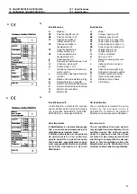
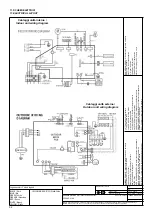
Connessioni elettriche dell'unità esterna.
* Rimuovere il pannello laterale e la scatola di protezione valvole
(se presente) locate nel medesimo lato.
* Inserire i cavi di alimentazione e di controllo tra unità interna
ed esterna attraverso il foro del pannellino laterale.
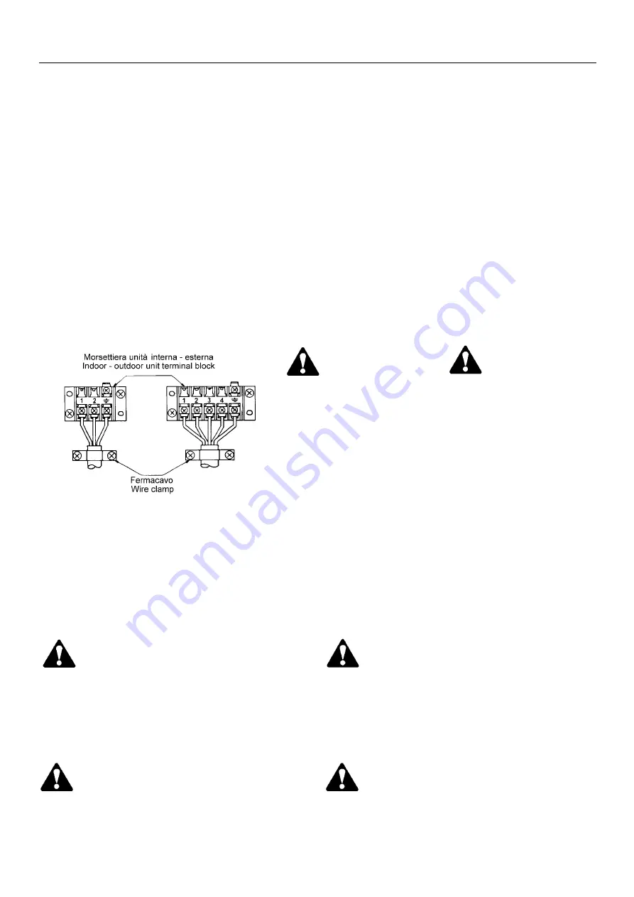
* Inserire i terminali del cavo di alimentazione nella morsettiera
in accordo con i colori e i numeri corrispondenti (fig.12) e
fissare le viti. Il filo giallo/verde si collegacon la massa a
terra.
* Collegare il connettore del cavo di controllo al corrispondente
connettore numerato nell'unità esterna (cfr. fig.12).
* Fissare i cavi di collegamento e controllo con il fermacavo.
* Installare il pannello laterale.
Outdoor unit wiring connections
* Remove the side plate in the outdoor unit valves side.
* Put the control and power wires between indoor and outdoor
units through the side panel hole.
* Insert the wires end into the holes in the terminal block
according to corresponding numbers and colours (see fig.12)
and fix the screws. Green/yellow cable is to be connected
with ground.
* Connect the control wire to the corresponding numbered
connector on the outdoor unit.
* Fix the control and power wires with the cable holder.
* Install the side panel.
9. INSTALLAZIONE
9. INSTALLATION
9.6. Installazione dell’unità esterna
9.6. Outdoor unit installation
FIG.12
ATTENZIONE
Si deve collegare il cavo rispettando lo schema elettrico.
Se il cablaggio non viene effettuato correttamente, il
climatizzatore si può danneggiare.
ATTENTION
The cable must be connected in compliance with the wiring
diagram. The air conditioner could be damaged if the con-
nections are incorrectly made.
39
Nei sistemi multisplit inverter collegare i conne-
tori numerati dall’unità interna con i corrispon-
denti dell’unità esterna.
In the inverter multisplit connect the connection
cablesto the terminals as identifiedwith their
respective matched numbers on the terminal
block of indoor and outdoor units.


