background image

Climatizzatore condensato


ad acqua On/Off

PICCOLO Mono

PICCOLO 12
PICCOLO 18

Rev.

 1.0

MANUALE


DI


USO


INSTALLAZIONE


PICCOLO

USE AND INSTALLATION 
MANUAL

 PICCOLO

On/Off water cooled


conditioning system

MANUEL


D’INSTALLATION


PICCOLO

Climatisation Invisible 

à


e

au


On/Off

Summary of Contents for PIC-12C6

Page 1: ...ua On Off PICCOLO Mono PICCOLO 12 PICCOLO 18 Rev 1 0 MANUALE DI USO E INSTALLAZIONE PICCOLO USE AND INSTALLATION MANUAL PICCOLO On Off water cooled conditioning system MANUEL D INSTALLATION PICCOLO Climatisation Invisible à eau On Off ...

Page 2: ......

Page 3: ...rizione Description MONOSPLIT ACQUA ARIA MONOSPLIT WATER TO AIR Modello Model PIC 12C6 PIC 18C6 Risulta in conformità con quanto previsto dalle seguenti direttive comprese le modifiche e con la relativa legislazione nazionale di recepimento 2004 108 CE 2006 95 CE 2003 108 CE 2011 65 CE 2012 2016 CE Is in compliance with the follow ECC direcrives latest modification included and the relevant nation...

Page 4: ......

Page 5: ...I T A L I A N O ...

Page 6: ......

Page 7: ...NTERNA 6 DISTANZE DI RISPETTO UNITÀ INTERNA 7 VERIFICHE PRELIMINARI 8 INSTALLAZIONE UNITÀ INTERNA 9 CONTROLLI DOPO L INSTALLAZIONE UNITÀ INTERNA 10 INSTALLAZIONE CONDENSANTE PICCOLO 11 AUTODIAGNOSI 12 MANUTENZIONE PICCOLO pagina capitolo 08 10 11 16 17 18 19 20 23 24 28 29 INDICE 7 13 PRECAUZIONE DI SICUREZZA NEELL USO DEL REFRIGERANTE R32 30 ...

Page 8: ...ravi lesioni o la morte alle persone esposte PERICOLO ALTE TEMPERATURE Richiama l attenzione su azioni che se non correttamente eseguite possono provocare gravi lesioni alle persone causate dall alta temperatura dei componenti INSTALLATORE Informazioni paragrafo capitolo del manuale che interessano l installatore CENTRO ASSISTENZA TECNICA Informazioni paragrafo capitolo del manuale che interessano...

Page 9: ...zi tecnici Alimentazione dell unità deve avvenire con cavi elettrici di sezione adeguata alla potenza della unità ed i valori di tensione di alimentazione devono corrispondere a quelli indicati per le rispettive macchine tutte le macchine devono essere collegate a terra come da normativa vigente nei diversi paesi INFORMAZIONI GENERALI manuale L apparecchio deve essere installato in maniera tale da...

Page 10: ...a 5 In caso di impurità presenti nell acqua eseguire una periodica manutenzione al filtro 6 Accertarsi che ai morsetti di collegamento elettrico arrivi la tensione corretta vedere targhetta di identificazione applicata sull apparecchiatura Una tensione non corretta comprometterebbe in modo irreparabile i principali componenti dell apparecchiatura 7 Nel caso si dovessero attivare allarmi consultare...

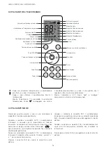
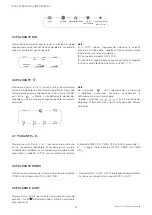
Page 11: ...Premere i pulsanti o per selezionare la temperatura desiderata Non può essere selezionata in modalità AUTO 3 Dopo aver alimentato l apparecchio premere il pulsante ON OFF sul telecomando per accenderle l apparecchio 4 Premere il pulsante FAN per selezionare la velocità di ventilazione desiderata auto fan1 fan2 fan3 fan4 fan5 InfinteSpeed 5 Premere il pulsante per selezionare la direzione del fluss...

Page 12: ... significa che il segnale è stato inviato al condizionatore Mentre l indicatore è OFF l icona light e orologio compariranno sul display del telecomando Quando si seleziona la modalità DRY il condizionatore funzionerà in modalità dry alla più bassa velocità impostabile fan1 In questa modalità non è possibile regolare la velocità dell aria Quando si seleziona la modalità FAN il condizionatore farà u...

Page 13: ...alità di funzionamento e delle temperature misurata e desiderata 2 Fan speed in modalità DRY è FAN1 3 Infinite fan speed mode consente all Utente di regolare la velocità di ventilazione attraverso i pulsanti o Nodisplay GUIDA UTENTE DELL UNITÀ INTERNA 3 7 PULSANTE E 3 8 PULSANTE TURBO Premere una volta il tasto o per aumentare o diminuire di 1 la temperatura desiderata Tenendoli premuti il valore ...

Page 14: ...ando inizierà a lampeggiare Premere o entro 5 secondi per regolare i minuti Ad ogni pressione dei tasti o l orologio aumenta o diminuisce di 10 min MANUALE INSTALLAZIONE PICCOLO Al cambiamento di modalità MODE le impostazioni SLEEP saranno cancellate Funzione non disponibile in modalità FAN e AUTO invierà le informazioni all unità interna Assicurarsi che il telecomando sia vicino all utilizzatore ...

Page 15: ...rifiuti per uno smaltimento corretto 3 1 FUNZIONALITÀ INTRODOTTE CON COMBINAZIONE DI PULSANTI Valore minimo di temperatura impostabile A macchina spenta premere insieme i pulsanti TEMP e Il display mostrerà la minima temperatura impostabile in raffrescamento default 31 C E possibile impostare un nuovo valore agendo sui tasti o da 16 C a 31 C Una ulteriore pressione dei tasti TEMP e riporta la macc...

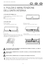
Page 16: ...eggiato e fresco 4 Inserire il filtro Inserire il filtro pulito e asciutto e chiudere il pannello 2 Rimuovere il filtro Rimuovere il filtro come mostrato in figura SCOLLEGARE ELETTRICAMENTE L APPARECCHIO PRIMA DI PULIRLO AL FINE DI EVITARE SCOSSE ELETTRICHE NON PULIRE L APPARECCHIO CON GETTI D ACQUA AL FINE DI EVITARE SCOSSE ELETTRICHE NON PULIRE L APPARECCHIO CON LIQUIDI AD ELEVATA VOLATILITÀ Il ...

Page 17: ... di tensione Togliere tensione all apparecchio ed alimentarlo dopo un attesa di almeno 180 sec L impostazione del telecomando è corretta Verificare Emette nebbiolina La temperatura e l umidità ambiente sono alte E un fenomeno naturale Al diminuire della temperatura e dell umidità il fenomeno si attenua Non si può modificare la temperatura desiderata L Unità è in modalità AUTO La temperatura deside...

Page 18: ...i devono essere ostacoli vicino ingresso e uscita dell aria 9 Selezionare una posizione in cui l acqua di condensa possa essere dispersa facilmente 10 Selezionare una posizione conveniente per collegare l Unità Esterna e vicino alla presa di corrente 11 Il luogo di installazione deve essere fuori dalla portata dei bambini 12 Il luogo d installazione deve essere in grado di sopportare il peso dell ...

Page 19: ...asse A La messa a terra deve essere effettuata con un dispositivo adatto alla messa a terra Assicurarsi che la messa a terra sia sempre rispettato altrimenti può causare scosse elettriche 2 Il cavo giallo verde nel condizionatore è il cavo della messa a terra il quale non può essere usato per altri scopi 8 Tagliatubi 9 Nastro di misurazione 10 Manometri 11 Carotatrice 12 Aspirapolvere 13 Cerca Fug...

Page 20: ...corrispondente foro sulla carrozzeria Dx 1 2 Sx Posteriore Dx Tubo tagliato scheda Posizionare la chiave aperta sul giunto del tubo ed inserirla sul dado Serrare il dado con la chiave 4 Avvolgere il tubo interno e il giunto di connessione con del tubo isolante e poi avvolgere il tutto con nastro adesivo Avvolgere con tubo isolante il tubo di scarico all interno al fine di prevenire la condensa Le ...

Page 21: ...ta lunghezza separare il tubo di scarico e il cavo di alimentazione come riportato in figura 3 Ricoprirli allo stesso modo Tutti i collegamenti tra Unità Interna e Unità Esterna dovrebbero essere effettuati da personale qualificato Se il cavo di alimentazione non è abbastanza lungo contattare il fornitore e chiederne uno nuovo Per i condizionatori con alimentazione tramite spina la spina deve esse...

Page 22: ...guatamente sulla parete Il tubo di scarico non deve essere eccessivamente ricoperto in modo da evitarne l ostruzione Il tubo di scarico deve seguire l inclinazione del foro nel muro come mostrato in figura Lo scarico dell acqua non può avvenire in acqua in modo da scaricare uniformemente Inclinare il tubo di scarico leggermente verso il basso Non può essere curvato gancio inferiore gancio superior...

Page 23: ...refrigerante Non è semplice decidere la carica di gas Rivolgersi all installatore o al centro assistenza 9 2 TEST DELL UNITÀ INTERNA 9 3 LE FASI DEL TEST OPERATIVO SONO LE SEGUENTI 1 Preparazione al test di funzionamento Il cliente approva la macchina appena montata Riferire al cliente qualsiasi informazione importante riguardo la macchina 2 Metodo del test di funzionamento Attaccare l alimentazio...

Page 24: ...i sui raccordi posti sul lato destro macchina I raccordi idraulici sono contrassegnati da etichetta con indicato il flusso INGRESSO ACQUA e USCITA ACQUA Prevedere un rubinetto di intercettazione sull ingresso acqua utilizzare tubazioni con diametro I collegamenti frigoriferi vengono effettuati sui raccordi posti sul lato destro macchina Il pannello frontale deve essere ispezionabile pertanto lo sp...

Page 25: ... In funzione della lunghezza di collegamento per singola via potrà risultare necessario un rabbocco della carica di refrigerante le motocondensanti sono precaricate per una linea di 5 metri Questa operazione dovrà essere effettuata da personale qualificato e a perfetta regola d arte del tecnico frigorista Il completamento di carica viene immesso decadimento della garanzia In caso di impiego di uni...

Page 26: ...na I collegamenti elettrici vengono effettuati sulla morsettiera che si trova all interno del vano componenti elettrici posto dietro al pannello di ispezione Allacciare il cavo sui morsetti all interno del quadro elettrico Evitare assolutamente contatti diretti con parti metalliche Assicurarsi dopo circa 10 minuti di funzionamento della motocondensante la chiusura delle viti sulla morsettiera di a...

Page 27: ...Sia fissata adeguatamente e stabile se montata su staffe controllare che gli antivibranti in gomma siano ben fissati tra macchina e staffa I collegamenti elettrici inclusa la messa a terra siano eseguiti in accordo alle leggi nazionali in vigore Le linee frigorifere siano sigillate controllare tutte le connessioni ventilanti Accertarsi del corretto deflusso dell acqua nello scarico utilizzato Cont...

Page 28: ... collegamento nella scheda elettronica U I L1 Errore del circuito zero crossing detection Sostituire scheda elettronica U E Nel caso si ripresentasse sostituire Unità PICCOLO L2 Errore motore ventola U I Verificare che il connettore del motore ventola U I sia inserito correttamente nell apposito collegamento nella scheda elettronica Se l errore persiste sostituire il motore ventilatore U I U0 Cort...

Page 29: ... sulla linea di bassa pressione Caricare la quantità di gas refrigerante indicata sulla targhetta tecnica dell apparecchio in fase liquida Eseguire sempre il controllo dei valori di surriscaldamento e sottoraffreddamento che devono essere compresi tra 4 e 8 C surriscaldamento e tra 5 e 10 C sottoraffreddamento In caso di perdita parziale il circuito deve essere svuotato completamente prima di esse...

Page 30: ...zione o l area della camera soddisfano i requisiti della targhetta È consentito operare solo nelle stanze che soddisfano i requisiti della targhetta Controllare se l area di manutenzione è ben ventilata Lo stato di ventilazione continua deve essere mantenuto durante il processo operativo Controllare se c è una fonte di fuoco o potenziale fonte di fuoco nell area di manutenzione La fiamma libera è ...

Page 31: ...re l etichetta sul sistema dopo aver completato il riempimento o non aver finito 4 Non riempire eccessivamente 5 Al termine del riempimento eseguire il rilevamento delle perdite prima dell esecuzione del test un altro momento di rilevamento delle perdite dovrebbe essere fatto quando viene rimosso 13 6 PRECAUZIONI DI SICUREZZA PER IL TRASPORTO E LO STOCCAGGIO 1 Utilizzare il rilevatore di gas infia...

Page 32: ......

Page 33: ...E N G L I S H ...

Page 34: ......

Page 35: ...TION ANALYSIS INDOOR UNIT 6 PLACE OF INSTALLATION INDOOR UNIT 7 PRELIMINARY CHECKS 8 INSTALLATION INDOOR UNIT 9 CHECKS AFTER INSTALLATION 10 INSTALLATION PICCOLO UNIT CONDENSING 11 SELF DIAGNOSIS 12 MAINTENANCE PICCOLO UNIT page chapter 36 38 39 44 45 46 47 48 51 52 56 57 INDEX 35 13 SAFETY PRECAUTION IN THE USE OF R32 58 ...

Page 36: ... or death to exposed persons DANGER HIGH TEMPERATURES Calls attention to actions that if not correctly performed may cause serious personal injury caused by the high temperature of the components INSTALLER Information paragraph section of the manual that affect the installer TECHNICAL ASSISTANCE CENTRE Information paragraph chapter of the manual that affect the service center IMPORTANT Calls atten...

Page 37: ...king sitting and or rest any type of object Do not spray or pour water directly on the unit You not dispose of abandon or leave within reach of children packaging materials cardboard staples plastic bags etc As it can be potentially dangerous hydraulic coupling must be performed as instructed to ensure proper operating condition If during the winter period the unit is not in operation it is necess...

Page 38: ...t in the water perform periodic filter maintenance 6 Make sure the electrical connection terminals are powered by the correct voltage see unit s identification plate An incorrect voltage will irreparably jeopardise the main components of the unit 7 If alarms are activated consult the user manual or contact the manufacturer s service assistance centre 8 Do not force for any reason the operation of ...

Page 39: ...gency switch outlet air horizontal flap filter U INS CAT inlet air 3 After powering up the device press the ON OFF button on the remote control to turn them on the device 4 Press the FAN button to select the desired fan speed Auto fan1 fan2 Fan3 fan4 fan5 InfinteSpeed 5 Press the buttons to select the direction of the air flow While using the remote control aim it in the direction Inner Unity The ...

Page 40: ...and then the direction of the air jet After you select the COOL mode the air conditioner will operate in cooling mode Press the and to adjust the temperature Press the FAN button to vary the air outlet speed When you select the DRY mode the air conditioner will operate in dry mode at the lowest speed setting fan1 In will beep which means that the signal has been sent to the air conditioner While t...

Page 41: ...de allows the user to adjust the fan speed by buttons or To prevent the release of cold air once set the indoor unit will delay of 1 5 min of air leakage the temperature range can be set from 16 to 31 C air speed Auto fan1 fan2 Fan3 fan4 fan5 and turbo Nodisplay USER GUIDE INDOOR UNIT 3 7 BUTTON E 3 8 BUTTON TURBO 3 9 BUTTON HEALTH Press the button once or to increase or decrease of one the desire...

Page 42: ...r decreases by 1 hour Pressing TIMER ON 0 00 in the remote control display will flash Press or within 5 seconds to adjust the minutes Each press of the buttons or the clock will increase or decrease by 10 minutes Pressing TIMER ON 0 00 in the remote control display will INSTALLATION MANUAL PICCOLO To change the MODE the SLEEP mode will be canceled The feature is not available in FAN and AUTO modes...

Page 43: ...ce versa Children safety Press and simultaneously to activate and deactivate the LOCK function The icon of the remote control will activate or deactivate accordingly minimum temperature settable value With the machine off press both buttons TEMP and The display will show the minimum temperature set in cooling mode default 16 C E can set a new value using the or from 16 C to 31 C A further press of...

Page 44: ...4 Insert the filter Insert the filter clean dry and close the panel 2 Remove the filter Remove the filter as shown in FIG ELECTRICAL DISCONNECT THE UNIT BEFORE ATTEMPTING TO CLEAN IT TO PREVENT SHOCK END DO NOT CLEAN THE APPLIANCE WITH JETS OF WATER TO AVOID ELECTRICAL SHOCK END DO NOT CLEAN THE APPLIANCE WITH LIQUID HIGH VOLATILITY The filter should be cleaned every three months If there is a lot...

Page 45: ...Lack of electricity Attendere fino al suo ripristino damaged electrical wiring Replaced by a qualified There was a sudden power surge Cut off the power and feed it after a wait of at least 180 sec Setting the remote control correct To verify emits fog The temperature and the ambient humidity are high It a natural phenomenon With decreasing temperature and humidity the phenomenon fades Can not be d...

Page 46: ...ly 7 Laundries 8 There must be no obstacles near the air inlet and outlet 9 Select a location where the condensate can be dispersed easily 10 Select a convenient location for connecting the outdoor unit and close to the power outlet 11 The place of installation must be out of reach of children 12 The place of installation must be able to withstand the weight Indoor Unit and should not increase noi...

Page 47: ...ioner is an electrical appliance in Class A The grounding should be performed with a suitable device to the ground Make sure the ground is always respected otherwise it may cause electric shock 2 The yellow green cable in the air conditioner is the cable of the ground which can not be used for other purposes 8 cutter 9 Measuring tape 10 Pressure gauges 11 Core drill 12 Vacuum cleaner 13 Search Get...

Page 48: ...the corresponding hole on the body Dx 1 2 Sx Right rear cut pipe chart Place the open ended wrench on the coupling of the tube and insert the nut Tighten the nut with a wrench 4 Wrap the inner pipe and the coupling connection with the insulating tube and then wrap the whole with adhesive tape Wrap with insulating tube inside the exhaust pipe in order to prevent condensation The expansion plastics ...

Page 49: ...er cable for installation After having them covered for a certain length separating the discharge tube and the power cable as shown in the figure 5 Close the panel All connections between Indoor and Outdoor Unit should be carried out by qualified personnel If the power cord is not long enough contact the vendor and request a new one For air conditioners with power via plug the plug must be attache...

Page 50: ...that the indoor unit is installed properly on the wall The drain hose must not be over coated in order to avoid the obstruction The drain hose must follow the angle of the hole in the wall as shown in FIG The water outlet can not take place in water so as to discharge smoothly Tilt the exhaust pipe down slightly It can not be bent lower hook upper hook sealing rubber outdoor indoor tube wall The c...

Page 51: ...the gas charge Ask your installer or service center 9 2 TEST THE INDOOR UNIT 9 3 STEPS OF THE OPERATIONAL TEST 1 Preparation the function test The customer approves the newly assembled machine To report to the customer any important information about the machine 2 the function test method Attach the power supply press the ON OFF button on the remote control to start the test Press the MODE button ...

Page 52: ...hydraulic connections are made on the connections located on the right side of the machine Flexible hydraulic hoses are marked with label indicated the flow WATER INLET and WATER OUTLET Provide a faucet water input interception use pipes with an inner diameter corresponding The refrigerant connections are made on the connections located on the right side of the machine The front panel must be insp...

Page 53: ...ing unit and Unit Inner In function of the connection length independent way it may be necessary to top up the refrigerant charge the condensing units are preloaded to a 5 meter line This operation must be performed by qualified personnel and in good standing of the art refrigeration engineer The completion of charging is introduced through the fitting service valve Flare of condensing invalidate ...

Page 54: ...rical connections are made on the terminal block that is located inside of the electrical components located behind the inspection panel Connect the cable to terminals inside the electrical panel Avoid direct contact with metal parts Ensure after about 10 minutes of operation of the condensing unit the closure of the screws on the power terminal 10 13 INSTALLATION OF PIPES FOR COOLING The main cau...

Page 55: ...ed Before applying voltage to the condensing unit to ensure that Both fixed properly and stable if mounted on brackets between the machine and check that the bracket are tight rubber vibration dampers The electrical connections including the earth are carried out in accordance with national laws The refrigerant connections are sealed check all connections Check the operating pressure high pressure...

Page 56: ...few seconds if the code occurs again after a few minutes please contact the professional person professional person L2 No feedback signal of indoor unit fan Turn off restart after a few seconds if the code occurs again after a few minutes please contact the professional person professional person U0 Short open circuit of indoor environment sensor Power off the unit restart after 10s if the code oc...

Page 57: ...utlet Connect the refrigerant cylinder to the gas outlet on the low pressure line Charge the quantity of refrigerant gas indicated on the rating plate of the device in the liquid phase Always check the undercooling values which must be between 4 and 8 C and between 5 and 10 C supercooling In the event of partial leaks the circuit must be completely emptied before being recharged The R32 refrigeran...

Page 58: ...t is allowed to operate only in rooms that meet the requirements of the plate Check if the maintenance area is well ventilated The continuous ventilation status must be maintained during the operating process Check if there is a source of fire or a potential source of fire in the maintenance area o potenziale fonte di fuoco nell area di manutenzione The free flame is forbidden in the maintenance a...

Page 59: ...lled 3 Attach the label on the system after completing the fill or not finished 4 Do not overfill 5 When filling is complete perform leak detection before running the test another moment of leak detection should be done when it is removed 13 6 SAFETY PRECAUTIONS FOR TRANSPORT AND STORAGE 1 Use the flammable gas detector to check before unloading and opening the container 2 No source of fire and sm...

Page 60: ......

Page 61: ...F R A N Ç A I S ...

Page 62: ......

Page 63: ...EMENTS DE L UNITÉ INTÉRIEURE 6 DISTANCES DE PROTECTION DE L UNITÉ INTÉRIEURE 7 CONTROLES PRELIMINAIRES 8 INSTALLATION DE L UNITÉ INTÉRIEURE 9 CONTRÔLES APRÈS L INSTALLATION 10 INSTALLATION PICCOLO 11 CODES D ERREUR 12 ENTRETIEN L UNITÉ PICCOLO 64 66 67 72 73 74 75 76 79 80 84 85 page chapitre INDEX 63 13 PRECAUTION DE SECURITE DANS L UTILISATION DE R32 86 ...

Page 64: ...a mort des personnes exposées si elles ne sont pas correctement exécutées DANGER HAUTES TEMPÉRATURES rappelle l attention sur les actions qui peuvent provoquer des graves blessures provoquées par la haute température des élémentssi elles ne sont pas correctement exécutées INSTALLATEUR informations paragraphe chapitre du manuelconcernant l installateur CENTRE D ASSISTANCE TECHNIQUE informations par...

Page 65: ...s de section adéquate à la puissance de l unité et les valeurs de tension d alimentation doivent correspondre à celles indiquées pour les respectives machines toutes les machines doivent être connectées à la terre conformément aux normes en vigueur dans les différents pays dans ce manuel L appareil doit être installé de manière à ne pas gêner les opérations d entretien et ou de réparation La garan...

Page 66: ...le filtre à eau fourni pour protéger l échangeur à plaques entrée d eau 5 En cas d impuretés présentes dans l eau effectuer un entretien périodique du filtre 6 S assurer que les bornes de connexion électrique sont alimentées par la bonne tension voir plaque d identification appliquée sur l appareil Une tension incorrecte peut compromettre irrémédiablement les composants principaux de l appareil 7 ...

Page 67: ...n modalité AUTO 3 Après avoir alimenté l appareil appuyer sur la touche ON OFF sur la télécommande pour démarrer l appareil 3 Appuyer sur la touche FAN pour sélectionner la vitesse de ventilation désirée auto fan1 fan2 fan3 fan4 fan5 InfinteSpeed 4 Appuyer sur les touches oscillation horizontale o oscillation vertical pour sélectionner la direction du flux d air Pendant l usage de la télécommande ...

Page 68: ...l n est pas possible régler la vitesse de l air Quand on choisit la modalité FAN climatiseur émettra un son ce que signifie que le signal a été envoyé au climatiseur Pendant que l indicateur est OFF l icône light2 et horloge afficheront sur le display de la télécommande le climatiseur permettra à l air de la température de sortir l environnement ne se chauffera ni se refroidira Après avoir choisi ...

Page 69: ...tesse optimale en fonction de la modalité de fonctionnement et des températures mesurées et désirées 2 Fan speed en modalité DRY et FAN1 3 Infinite fan speed mode consent à l Usager de régler la vitesse de ventilation à travers les touches o Nodisplay 3 7 TOUCHE E 3 8 TOUCHE TURBO Appuyer une fois sur la touche o pour augmenter ou diminuer de 1 la température désirée En appuyant sur les deux la va...

Page 70: ...encore TIMER ON sur le display 00 00 la télécommande commence à clignoter Appuyer sur o dans 5 secondes pour régler les minutes A chaque pression de touches o l horloge MANUEL D INSTALLATION PICCOLO Pour changer le MODE le mode de sommeil sera annulé La fonction est disponible en mode FAN et AUTO Note S assurer que la télécommande soit près de l utilisateur à l abri des sources de chaleur ou d env...

Page 71: ... 3 sec Pour activer ou désactiver la modalité Intelligent Defrost Note Modalité de défaut en état d activation et pas en état de désactivation Température de configuration environnementale basse LA En modalité HEATING tenir appuyé sur les touches SLEEP et TURBO pendant 3 sec Pour activer ou désactiver la modalité Intelligent Defrost L icône correspondante LA sera affichée dans le display de la tél...

Page 72: ...érer le filtre nettoyé et sec et arrêter le panneau 2 Enlever le filtre Enlever le filtre comme montré en Illustration DÉCONNECTER ÉLECTRIQUEMENT L APPAREIL AVANT DE LE NETTOYER AU BUT D EMPÊCHER LES SECOUSSES ÉLECTRIQUES DÉCONNECTER ÉLECTRIQUEMENT L APPAREIL AVANT DE LE NETTOYER AU BUT D EMPÊCHER LES SECOUSSES ÉLECTRIQUES NE PAS NETTOYER L APPAREIL PAR DU LIQUIDES À VOLATILITÉ ÉLEVÉE Le filtre do...

Page 73: ...fusibles Il faut vérifier la cause de l intervention par le personnel qualifié et le remettre en service Câblage électrique endommagé Il faut le remplacer par le personnel qualifié L UI émet brouillard La température et l humidité environnementale sont hautes C est un phénomène naturel Avec la diminution de la température et de l humidité le phénomène s atténue On ne peut pas modifier la températu...

Page 74: ... qui ne sont habitables en toute sécurité 8 Blanchisserie 9 Il ne faut pas qu en proximité de l entrée ou en sortie d air ils y aient des obstacles 10 Choisir une position dans laquelle l eau de condensation puisse être facilement dispersée 11 Sélectionner une position convenable pour connecter l unité extérieure près de la prise de courant 12 Le lieu d installation doit être hors de la portée des...

Page 75: ... La mise à terre doit être effectuée par un dispositif approprié à la mise à terre S assurer que la mise à terre soit toujours respectée autrement il peut causer des secousses électriques 2 Le câble jaune verte dans le climatiseur représente le câble de mise à terre lequel ne peut pas être utilisé pour d autres buts 8 Coupes tubes 9 Recherches de fuites 10 Pompe à vide 11 Manomètres 12 Mètre 13 Cl...

Page 76: ...droite ou gauche il faut pratiquer le correspondent trou sur le corps Dx 1 2 Sx Postérieur droite Tube coupé Positionner la clé ouverte sur le joint du tube et l insérer sur l écrou Serrer l écrou par la clé dynamométrique 4 Envelopper le tube intérieur et le joint de connexion par le tube isolant et puis envelopper l ensemble par ruban adhésif Envelopper par un tuyau isolant le tuyau de décharge ...

Page 77: ... décharge et le câble d alimentation comme rapporté dans l illustration 3 Recouvrez le à la même manière 5 Serrer le panneau Toutes les connexions entre unité intérieure et extérieure doivent être effectuées par le personnel qualifié Si le câble d alimentation n est pas suffisamment long remplacez le Pour les climatiseurs à alimentation par fiche il faut attaquer la fiche après avoir terminé l ins...

Page 78: ...r que l unité intérieure soit installée de manière adéquate Le tuyau de décharge ne doit pas être excessivement recouvert en manière d empêcher les obstructions Le tuyau de décharge doit suivre l inclinaison du trou dans le mur comme montre en illustration Le déchargement de l eau ne peut pas s effectuer en eau pour vider uniformément Incliner le tuyau de décharge légèrement vers le bas Ne peut pa...

Page 79: ...arge du gaz réfrigérant Il faut s adresser à l installateur ou à l assistance 9 2 TEST DE L UNITÉ INTÉRIEURE 9 3 LES PHASES DU TEST OPÉRATIONNEL SONT LES SUIVANTS 1 Préparation au test de fonctionnement Le client approuve la machine qui vient d être installée Référer au client n importe quelle information importante par rapport à la machine 2 Méthode du test de fonctionnement Brancher l alimentati...

Page 80: ...tions 2 ou plus IDRA NE PAS SUPERPOSER les unités de condensation L installation doit permettre au personnel qualifié et autorisé de pouvoir intervenir en cas d entretien de manière simple en respectant les distances de sécurité entre l unité et les autres appareils et les espaces techniques indiqués ci dessous 10 2 CIRCUITS HYDRAULIQUES ET FRIGORIFIQUES L installateur est responsable du choix et ...

Page 81: ...é de gaz neutre Par conséquent après avoir effectué les raccordements il faudra vider l air contenu dans ces connexions et dans les unités intérieures 10 9 PROCÉDURE DE MONTAGE L unité de condensation IDRA INVERTER DOIT ÊTRE INSTALLÉEdans une position accessible pour pouvoir effectuer d éventuelles interventions techniques en toute sécurité Dans le cas contraire les SAV centre d assistance techniq...

Page 82: ...appareil Les connexions électriques sont effectuées sur le bornier situé à l intérieur du boîtier électrique monté derrière le panneau de contrôle Brancher le câble aux bornes à l intérieur du panneau électrique Éviter tout contact direct avec des pièces métalliques S assurer après environ 10 minutes de fonctionnement de l unité de condensation la fermeture des vis sur le bornier d alimentation 10...

Page 83: ...ation utilisé Contrôler la pression de fonctionnement haute pression au moyen d un groupe monomètrique pour vérifier le bon fonctionnement de la vanne pressostatique 10 15 MISE EN MARCHE DE L UNITÉ DE CONDENSATION Avant d alimenter l unité de condensation s assurer que Elleest correctement fixée et suffisamment stable si elle est montée sur des supports vérifier que les caoutchoucs anti vibrations...

Page 84: ...E2 Protection contre les surcharges du compresseur HE Erreur compresseurécart quadratique moyen L0 Erreur configuration jumper L1 Erreur du circuit zero crossing detenction L2 Erreur moteur ventilateur unité intérieure U0 Court circuit capteur de température ambiante U I U1 Erreur du capteur de températures du tuyau intérieur b3 Alert de nettoyage du filtre SAV 84 ...

Page 85: ...nt ou un cylindre de remplissage à la prise sur la ligne de basse pression Charger la quantité de fluide réfrigérant indiqué sur l étiquette technique de l appareil Vérifier toujours les valeurs de surchauffe et de sous refroidissement celles ci doivent être comprises entre 4 et 8 C surchauffe et entre 5 et 10 C sous refroidissement Tension électrique d alimentation Absorption électrique Serrage d...

Page 86: ...ce ou la chambre répond aux exigences de la plaque signalétique Il est permis de ne travailler que dans des locaux conformes aux exigences de la plaque Vérifiez si la zone de maintenance est bien ventilée L état de ventilation continue doit être maintenu pendant le processus d exploitation Vérifiez s il y a une source d incendie ou une source potentielle d incendie dans la zone de maintenance La f...

Page 87: ...érant est rempli 3 Attachez l étiquette au système une fois le remplissage terminé ou non terminé 4 Ne pas trop remplir 5 Effectuer une détection de remplissage avant d exécuter le test un autre moment de détection de fuite devrait être fait quand il est enlevé 13 6 PRÉCAUTIONS DE SÉCURITÉ POUR LE TRANSPORT ET LE STOCKAGE 1 Utilisez le détecteur de gaz inflammable à vérifier avant de décharger et ...

Page 88: ......

Page 89: ......

Page 90: ......

Page 91: ......

Page 92: ...TEKNO POINT ITALIA S R L Via dell Artigianato 5 30020 Marcon VE IT Tel 041 5020421 Fax 041 5029514 commerciale teknopoint com www teknopoint com www climainvisibili it YTP MUI PIC 19ITA ENG FRA ...

Reviews: