background image

Shock Filling Instructions

For both front and rear shocks

17

The following steps and information will provide you with the proper way to fill and bleed your shocks.  

After thorough testing, we've found it's easiest to complete steps 1 through 3 on each shock before moving 

onto step 4.  By the time you've finished step 3 on the last shock the first one will be ready for step 4.

Standard or Vented Cap Build:

Step 1.  Extend the shock shaft all the way down.  Fill the shock with oil until the body is approximately 90% full.

Step 2. Slowly pump the shock shaft up and down 3-5 times to release air bubble from underneath the piston.

Step 3. Let the shock rest vertically with the shock shaft fully extended for five minutes or until all the air bubbles 

have released.

Step 4. Push the shaft in for the amount of rebound desired.  For example, to achieve 0% rebound push the shaft 

in all the way (in this case, about ¼” of shaft showing).  For 50% rebound, push the shaft in half way.  Make sure 

that you match the rebound amount between the left and right shocks.  We've found that running 0% rebound 

in both front and rear shocks gives great overall performance.  

Step 5. Next you will top off the shock with oil.  The goal is not to fill the body to the brim but only to fill it enough 

so that when the bladder is placed on top there will be no air underneath.  If you do overfill the shock, it won’t hurt 

performance, it will just spill out and make a little bit of a mess.

Step 6. In this step you will be placing the bladder on top of the shock body.  While holding the shock shaft in the 

desired position from step 4, push the bladder down onto the shock body using your fingertip to fully seat the lip 

of the bladder onto the rim of the shock body.  If done correctly a small amount of oil should bleed out.  If no oil is 

released you may have some air trapped underneath the bladder and you will need to remove the bladder and 

repeat step 5.  Once the bladder is seated onto the shock body, pull the shock shaft down about 20mm.  This will 

“suck” the bladder down and hold it in place.  Carefully wipe away the excess oil that was bled, being careful not 

to disrupt the seal of the bladder on the shock body.

Step 7. While continuing to hold the shock vertically, screw the shock cap down onto the body and tighten fully.  

The cap will bottom out easily, but the bladder will be sealed tight.  You can use an adjustable wrench to hold the 

bottom of the shock while tightening the shock cap down to be sure they are tight.

Emulsion Build:

Prep your shock caps TKR6018 (optional for EB48) accordingly by drilling out the large angled bleeder hole in the 

top of the cap.  Place the larger thin o-rings around the base of the threads where the shock cap screws on 

(see diagram).  This will seal the cap and the shock body.

Follow steps 1-3 above.

Step 4. Rebound is more of a natural side effect of an emulsion shock.  It’s not something that can be set accurately 

because you run the risk of hydrolocking the shock if you do not push the shaft all the way in when you bleed it.  

For now leave the shaft fully extended.

Step 5. Fill the shock all the way to the top, going over just slightly without spilling to create a small dome.

Step 6. Place a little bit of oil in the shock cap and quickly put the shock cap on the shock body.  Tighten the cap all 

the way down.  Very slowly push the shaft in.  Oil will start to bleed out of the top of the cap.  While wiping away 

excess oil, continue to slowly push the shaft in ALL THE WAY.  If no oil comes out when the shaft is fully inserted, 

you will need to add more oil and repeat the step.  Use the supplied M4x6mm flat head screw and TKR5125 o-ring 

to seal the cap.

Use part #’s TKR6008 (pistons and guides) and TKR6009 (o-ring pack) to rebuild your shocks regularly.

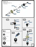
Summary of Contents for SCT410 X

Page 1: ......

Page 2: ...an indoor facility Use caution while operating vehicle so as not to collide with people who may be turn mashalling or who might otherwise not be aware that a fast moving RC vehicle is in the vicinity...

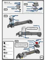
Page 3: ...Step A 2 TKR1325 M3x14mm Flat Head Screw x4 TKR5144 TKR5145 Step A 1 Fill with 5000 wt oil to the top of spider gears TKRBB08165 Ball Bearing 8x16x5mm x2 TKR5144 Differential 0 rings x2 TKR5145 Diffe...

Page 4: ...t for rear diff TKRBB08165 Ball Bearing 8x16x5mm x4 TKR5144 Differential 0 rings x4 TKR5145 Differential Shims 6x17mm x4 TKR5614 TKR5614X Option TKR5614 TKR5614X Option TKR5113 TKR5111 TKR5143 TKR5149...

Page 5: ...the diff binds and does not turn freely it will make a grinding or crunching sound when spun remove one TKR1222 shim from the gear side and install it onto the other side of the diff Reassemble and te...

Page 6: ...e to next step If the diff binds and does not turn freely it will make a grinding or crunching sound when spun remove one TKR1222 shim from the gear side and install it onto the other side of the diff...

Page 7: ...r tighten TKR1522 TKR1522 M3x8mm Cap Head Screw x2 TKR1601 M3x4mm Set Screw x6 Bag E Rear End Stock Position Outer Option TKR5080 2 2mm TKR5081 2 3mm TKR5083 2 5mm TKR5084 2 6mm TKR5085 2 8mm TKR5087...

Page 8: ...lity and is recommended for bumpy open tracks Inside hole offers greater amount of steering and is recommended for flat technical tracks A B A B Note TKR5540T1 hubs are NOT left right interchangeable...

Page 9: ...tion is 2 B TKR1529 TKR1201 Right TKR5051 This side mounts on hub Note no flange This side mounts on shock tower Note flange TKR5051 Left TKR5050 TKR1201 M3 Locknut Black x4 TKR1529 M3x20mm Cap Head S...

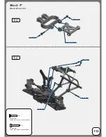
Page 10: ...TKR1528 M3x18mm Cap Head Screw x2 Step F 5 TKR1327 M3x16mm Flat Head Screw x4 Step F 6 Note Top side up Bag F Rear Bumper 10 TKR1327 TKR1327 TKR1327 TKR1327 TKR1528...

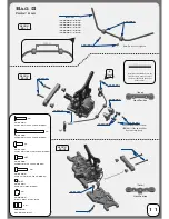
Page 11: ...ote Do not over tighten TKR1601 TKR1522 TKR1522 M3x8mm Cap Head Screw x2 TKR1601 M3x4mm Set Screw x6 Bag G Front End Option TKR5080 2 2mm TKR5082 2 4mm TKR5083 2 5mm TKR5084 2 6mm TKR5085 2 8mm TKR508...

Page 12: ...dle Pin Sleeve x4 TKR5555 Suspension Pin Sleeve x4 TKR5554A Option TKR5555A Option Step H 1 Step H 2 Grease TKR6856 TKR6856 TKR1213 M4 Lock Nut Flange Black x2 TKRBB10154 Ball Bearing 10x15x4 x2 TKRBB...

Page 13: ...KR5051 TKR5052 This side mounts on hub Note no flange This side mounts on shock tower Note flange TKR5053 Right TKR5051 This side mounts on hub Note no flange This side mounts on shock tower Note flan...

Page 14: ...ng is 1 washer above and 3 washers below the steering ball link 1 x TKR1221 3 x TKR1221 TKR1221 TKRBB06103 TKR5122 TKR1529 TKR1323 M3x10mm Flat Head Screw x2 TKR1201 M3 Lock Nut Black x2 O ring 16x12x...

Page 15: ...ering ball link TKR1327 TKR1344 TKR5518 TKR1529 TKR1528 M3x18mm Cap Head Screw x2 TKR1346 M4x15mm Flat Head Screw x2 TKR1343 M4x10mm Flat Head Screw x2 TKR1344 M4x12mm Flat Head Screw x4 TKR1201 M3 Lo...

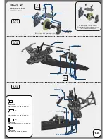
Page 16: ...3 M4x10mm Flat Head Screw x5 TKR1443 M4x10mm Button Head Screw x2 TKR1344 M4x12mm Flat Head Screw x7 TKR5217 Option TKR5577 Option Step K 1 Step K 2 Step K 3 Thread Lock Thread Lock Note If running Tr...

Page 17: ...bleed out If no oil is released you may have some air trapped underneath the bladder and you will need to remove the bladder and repeat step 5 Once the bladder is seated onto the shock body pull the s...

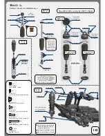
Page 18: ...ock bodies TKR6002 shorter shock shafts TKR6004 shorter springs TKR6048 and shorter shock boots TKR6023 Note Use green slime or oil on shock shaft threads AND O rings to prevent tearing and leaking TK...

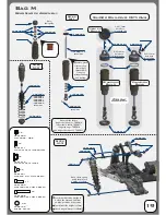
Page 19: ...r shock bodies TKR6016 longer shock shafts TKR6017 longer springs TKR6030 and longer shock boots TKR6023 Note Use green slime or oil on shock shaft threads AND O rings to prevent tearing and leaking T...

Page 20: ...KR1401 RX not included Transponder not included TKR1401 M3x6mm Button Head Screw x6 TKR1322 M3x8mm Flat Head Screw x5 TKR1525 M3x14mm Cap Head Screw x6 TKR5125 O ring 3x7mm x3 TKR1221 M3X8mm Washer x4...

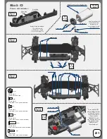
Page 21: ...m Flat Head Screw X5 TKR1445 M4x14mm Button Head Screw X2 TKR1227 M4x9mm Washer X2 Logo side Thread Lock Thread Lock Thread Lock TKR1523 M3x10mm Cap Head Screw x2 Bag O Final Assembly 21 Step O 2 Step...

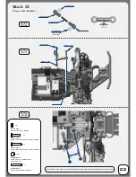
Page 22: ...ck x2 TKR5230 M3x18 Threaded Rod x1 TKR5058 TKR1405 TKR1201 TKR1201 TKR1407 TKR5230 TKR5056 TKR5058 TKR5056 Note Offset servo arm so it is parallel with the connecting arm at neutral or zero servo pos...

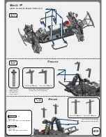
Page 23: ...atches your specific body holes Choose the post with the angle that matches your specific body 10mm offset 15 angled 0mm offset 5 angled 0mm offset 15 angled TKR1407 TKR1525 TKR1525 TKR1407 M3x16mm Bu...

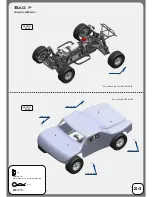
Page 24: ...Bag p Wheels Body 24 Step P 4 Step P 5 TKR1213 TKR1223 TKR1223 TKR1223 TKR1223 TKR1223 Body Clip x4 TKR1213 M4 Lock Nut Flange Black x4 Note Wheels and Tires NOT INCLUDED Note Body NOT INCLUDED...

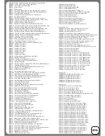
Page 25: ...10 f r hardened steel lightened TKR5576 Driveshaft SCT410 center rear hardened steel TKR5577 Driveshaft SCT410 center front 7075 aluminum gun metal ano TKR5578 Driveshaft SCT410 center front hardened...

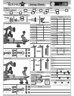
Page 26: ...N SPRING REBOUND SHOCK LENGTH DROOP STD EMUL VENT REAR Differential Oil Electronics FRONT COMPOUND INSERT ESC Battery Motor Radio Servo WHEEL NOTES BRAND TREAD REAR Traktion Drive Pinion teeth SPUR GE...

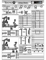
Page 27: ...N SPRING REBOUND SHOCK LENGTH DROOP STD EMUL VENT REAR Differential Oil Electronics FRONT COMPOUND INSERT ESC Battery Motor Radio Servo WHEEL NOTES BRAND TREAD REAR Traktion Drive Pinion teeth SPUR GE...

Page 28: ...www teknorc com Tekno RC 10755 Scripps Poway Pkwy 598 San Diego CA 92131 USA...

Reviews: