Customizing The Board 5-10
Example:
Assume the TEK-AT4L
PLUS
is powered by a 9V DC battery and it is required that the
battery be monitored for a low battery warning at 7.5V DC. In this case, R19=4700
Ω
and
R18=1000
Ω
.
So, if the battery voltage goes below 7.5V, it will generate a non-maskable interrupt
(NMI) and the status can be read at address 201 bit D3. If bit D3 is 0, a low battery is
indicated.
Bear in mind that R19 and R18 should be tailored to fit your specific application. The
values for these two resistors can be identified by using the following formula:
R18 / ( R19+R18) x 7.5V < 1.3V
where: R19 = 1000 x Vmon -1300 / 1.3
Please contact our Technical Support department if more details are needed.
WARNING
: All TEK-AT boards are equipped with an onboard detection circuit
which is activated when +5V drops below 4.75V. When this occurs, the
system is reset disabling access to SRAM, DRAM, and so on.
5.9.4
Low Battery Detection
The Low Battery Voltage detection uses the same circuit as the Power Failure Detector,
and thus, both cannot be used at the same time.
The Low Battery Detector generates an NMI when the battery voltage drops below 3 volts.
To monitor a Low Battery Voltage, install jumper W7(2-3) and jumper W13. The status
of PDO can be read back at I/O port 201 hex D3.
WARNING
: Although the Low Battery Detector uses the same circuit as the Power
Failure Detector, J5-6, R19 and R18 are not utilized. Instead, we have
added two other resistors for this function: R14 and R17.
5.10 Attaching the AT4L
PLUS
to Enclosure
Four mounting holes are available on the board to ensure an optimal mechanical fixing. It
is highly recommended to use all the mounting holes when attaching the TEK-AT4L
PLUS
to its enclosure.
Precise mounting holes location is given in the Appendices: TEK-AT4L
PLUS
- Mounting
Holes
.
Summary of Contents for TEK-AT4L Plus
Page 7: ...PRODUCT DESCRIPTION 1 PRODUCT OVERVIEW 2 ONBOARD SUBSYSTEMS...
Page 9: ...Product Overview 1 2 TEK AT4LPLUS Block Diagram...
Page 26: ...Installing Devices 6 3 CONNECTOR LOCATION...
Page 35: ...Setting Jumpers 8 3 JUMPER LOCATIONS...
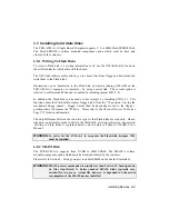
Page 36: ...Setting Jumpers 8 5 TABLE 8 1 Jumper Settings W1 W11...
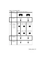
Page 37: ...Setting Jumpers 8 6 TABLE 8 2 Jumper Settings W12 W19 W26...
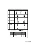
Page 38: ...Setting Jumpers 8 7 TABLE 8 3 Jumper Settings W20 W25 SW1 SW2...
Page 41: ...APPENDICES A PRODUCT SPECIFICATIONS B BOARD DIAGRAMS C CONNECTOR PINOUTS...
Page 43: ...Board Diagrams B 1 B 1 TEK AT4LPLUS Assembly Diagram Top View...
Page 44: ...Board Diagrams B 3 B 2 TEK AT4LPLUS Mounting Holes...
Page 45: ...Board Diagrams B 5 B 3 TEK AT4LPLUS Mechanical Specifications...


