Setting Jumpers 8-1
8. SETTING JUMPERS
The TEK-AT4L
PLUS
is designed to allow for minimal hardware configuration.
The following is a list of the basic configuration jumpers available on the board:
Jumper
Function
Jumper
Function
W1
Serial In 2 (SIN2)
W15
BIOS Boot Flash
W2
Request To Send 2 (RTS2)
W16
TEKNOR Extension
W3
CTS2 to RTS2
W17-19, W26
CPU Type Selection
W4
DTR2 to DSR2
W19A
PS/2 Mouse
W5
Serial Out 2 (SOUT2)
W20
Bus Clock Signal Selection
W6
CTS2
W21
CPU Clock Selection
W7(1-2)
Power Fail Detection
W22
Graphic Mode Selection
W7(3-4)
Low Battery Detection
W23-W24
DMA Channel Selection
W8
EDOUT (Floppy)
W25
Parallel Port Interrupt
W9
DHOUT (Floppy)
W26
CLKMUL Enable
W10
SRAM Battery Backup
W27
CPU power (3.3V or 5V)
W11
IDE Hard Disk Interface
SW1(1-2)
Boot from Flash
W12
Watchdog Timer
SW1(3-4)
COM1/COM2 Selection
W13
Power Monitoring
SW1(5-6)
Selects VT100 as Console
W14
Flash EPROM Write
SW1(7-8)
Download Mode
Summary of Contents for TEK-AT4L Plus
Page 7: ...PRODUCT DESCRIPTION 1 PRODUCT OVERVIEW 2 ONBOARD SUBSYSTEMS...
Page 9: ...Product Overview 1 2 TEK AT4LPLUS Block Diagram...
Page 26: ...Installing Devices 6 3 CONNECTOR LOCATION...
Page 35: ...Setting Jumpers 8 3 JUMPER LOCATIONS...
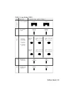
Page 36: ...Setting Jumpers 8 5 TABLE 8 1 Jumper Settings W1 W11...
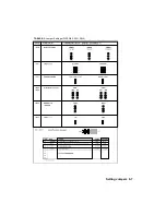
Page 37: ...Setting Jumpers 8 6 TABLE 8 2 Jumper Settings W12 W19 W26...
Page 38: ...Setting Jumpers 8 7 TABLE 8 3 Jumper Settings W20 W25 SW1 SW2...
Page 41: ...APPENDICES A PRODUCT SPECIFICATIONS B BOARD DIAGRAMS C CONNECTOR PINOUTS...
Page 43: ...Board Diagrams B 1 B 1 TEK AT4LPLUS Assembly Diagram Top View...
Page 44: ...Board Diagrams B 3 B 2 TEK AT4LPLUS Mounting Holes...
Page 45: ...Board Diagrams B 5 B 3 TEK AT4LPLUS Mechanical Specifications...


