BIOS Setup Error Codes
E-5
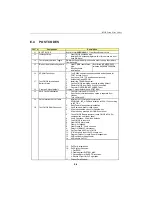
E.4 POST CODES
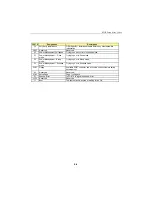
POST #
Designation
Description
01
BOOT BLOCK
Boot Block in EMERGENCY : Clear Base Memory Area.
03
Initialize Chips
1. Clear CMOS shutdown byte.
2. Initialize EISA extended registers. (Not for us since we don’t
have EISA bus.)
04
Test Memory Refresh Toggle
RAM must be periodically refreshed in order to keep the memory
from decaying.
05
Blank Video, Initialize Keyboard
1. Clear CMOS reset status
byte.
2. Early Keyboard
initialization.
Boot Block in EMERGENCY:
Initialize Keyboard Controller.
06
EPROM Checksum
1. Test F000h segment shadow readable and writeable for
POST access correct.
If not, show POST FE and beep continuously…
2. Autodetect Flash EPROM.
07
Test CMOS Interface and
Battery Status
1. Install the TEKNOR segment.
2. Verifies CMOS is working correctly (walking bit test).
3. Restore CMOS from Flash if option is enabled.
4. Check for OVERRIDE KEY (INSERT key).
08
Program Chipset default
Program Chipset default (show POST BEh).
09
Early Cache Initialization
1. Check for Intel’s and/or Cyrix CPU.
2. Early Cache Initialization when cache is separate from
chipset.
3. Turn off Gate A20.
0A
Setup Interrupt Vector Table
1. Initialize first 120 interrupt vectors with
SPURIOUS_INT_HDLR and initialize int. 00h-1Fh according
to INT_TBL.
2. Early Power Management Initialization.
0B
Test CMOS RAM Checksum
1. Verify time and date for valid values.
2. If Override enabled, check for Override key.
If Override key pressed, Kill CMOS checksum.
3. Check CMOS Battery (useless if save CMOS in FLASH
enabled since it’s already done).
4. Verify Checksum, if bad, load defaults.
5. Copy CMOS in the stack.
6. Clear CMOS Alarm date.
7. Clear HD if Hidden.
8. Clear Floppy "B" if only one drive.
9. Detect for a Math Co-processor.
10. Set Fast Gate A20 Flag in CMOS.
11. If "B" drive only is set the 2 Drive are set…
12. Program Chipset for early Power Management.
13. P6 Bios Update (if applicable).
14. Kill Onboard PnP IO.
15. PnP Early Initialization.
16. PnP System Resource:
1. Get ESCD.
2. Create default SYSTEM_MAP.
3. Decode/Record ISA ESCD resources.
4. Record I/O port for PnP operation.
17. Chipset Early Shadow.
Summary of Contents for TEK-CPCI 1003
Page 15: ...TEK CPCI 1003 Technical Reference Manual 5 4 5 1 CONNECTOR LOCATION...
Page 22: ...FEATURE DESCRIPTION 7 ONBOARD FEATURES...
Page 51: ...TEK CPCI 1003 Technical Reference Manual 9 2 JUMPER LOCATION...
Page 52: ...Setting Jumpers 9 3 JUMPER SETTINGS Table 1...
Page 53: ...TEK CPCI 1003 Technical Reference Manual 9 4 JUMPER SETTINGS TABLE 2...
Page 67: ...SOFTWARE SETUPS 12 AWARD SETUP PROGRAM 13 UPDATING THE BIOS WITH UPGBIOS 14 VT100 MODE...
Page 95: ...C 1 C BOARD DIAGRAMS C 1 ASSEMBLY TOP DIAGRAM...


