TEK-CPCI-1003 Technical Reference Manual
7-2
3.
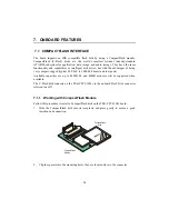
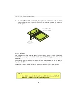
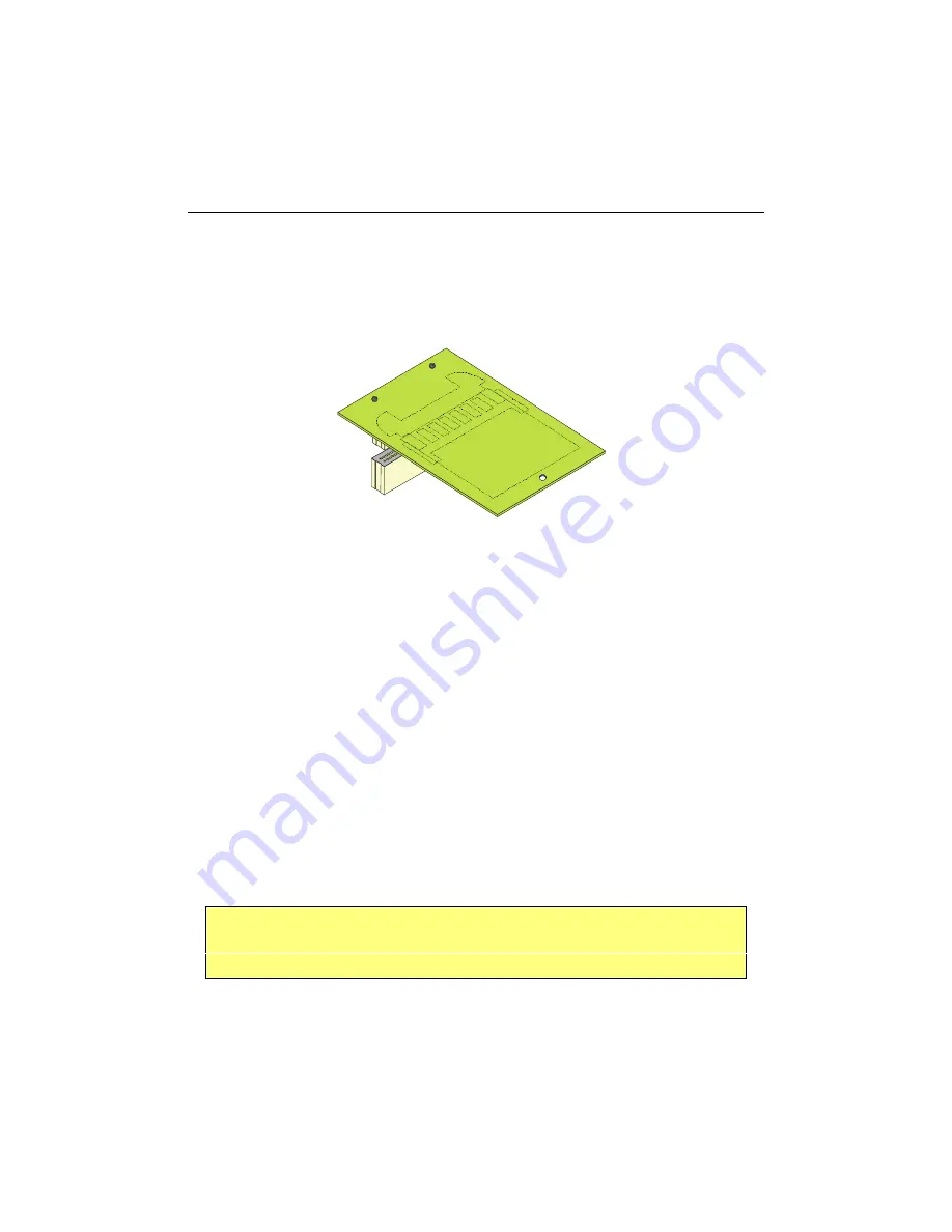
To connect the module to the SBC, line up the J11 connector and the module’s
connector, and then press the module firmly into the connector to engage the connector
and the spacers.
7.1.2 Setups
The CompactFlash disk connects directly on the Primary EIDE interface. It must be
declared the same way as a standard hard disk using the BIOS setup program (Autodetect
Function).
To setup the CompactFlash disk for Master or Slave configuration, use the W5 jumper
located on the SBC.
To locate and install a jumper cap on W5, please refer to Section 10 –
Setting Jumpers
.
NOTE
Since data is accessed like it would on an IDE drive, no specific flash
disk driver is required for various operating systems.
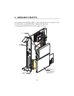
CompactFlash Module
+
CompactFlash Disk
Onboard
CompactFlash
Connector
Summary of Contents for TEK-CPCI 1003
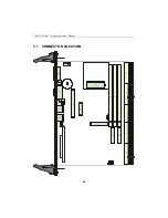
Page 15: ...TEK CPCI 1003 Technical Reference Manual 5 4 5 1 CONNECTOR LOCATION...
Page 22: ...FEATURE DESCRIPTION 7 ONBOARD FEATURES...
Page 51: ...TEK CPCI 1003 Technical Reference Manual 9 2 JUMPER LOCATION...
Page 52: ...Setting Jumpers 9 3 JUMPER SETTINGS Table 1...
Page 53: ...TEK CPCI 1003 Technical Reference Manual 9 4 JUMPER SETTINGS TABLE 2...
Page 67: ...SOFTWARE SETUPS 12 AWARD SETUP PROGRAM 13 UPDATING THE BIOS WITH UPGBIOS 14 VT100 MODE...
Page 95: ...C 1 C BOARD DIAGRAMS C 1 ASSEMBLY TOP DIAGRAM...


