TEK-CPCI-1003 Technical Reference Manual
7-4
7.3 ETHERNET INTERFACES
Both Ethernet controllers reside on the Primary PCI bus and are therefore Plug and Play by
default. No manual configuration is required.
Each interface supports 10Base-T and 100Base-TX specifications: 10Mbps and 100Mbps
network speeds are automatically detected and switched.
SIGNAL PATH
Ethernet signal path depends on the output configuration you have ordered for the
board.
§
Front Plate Configuration
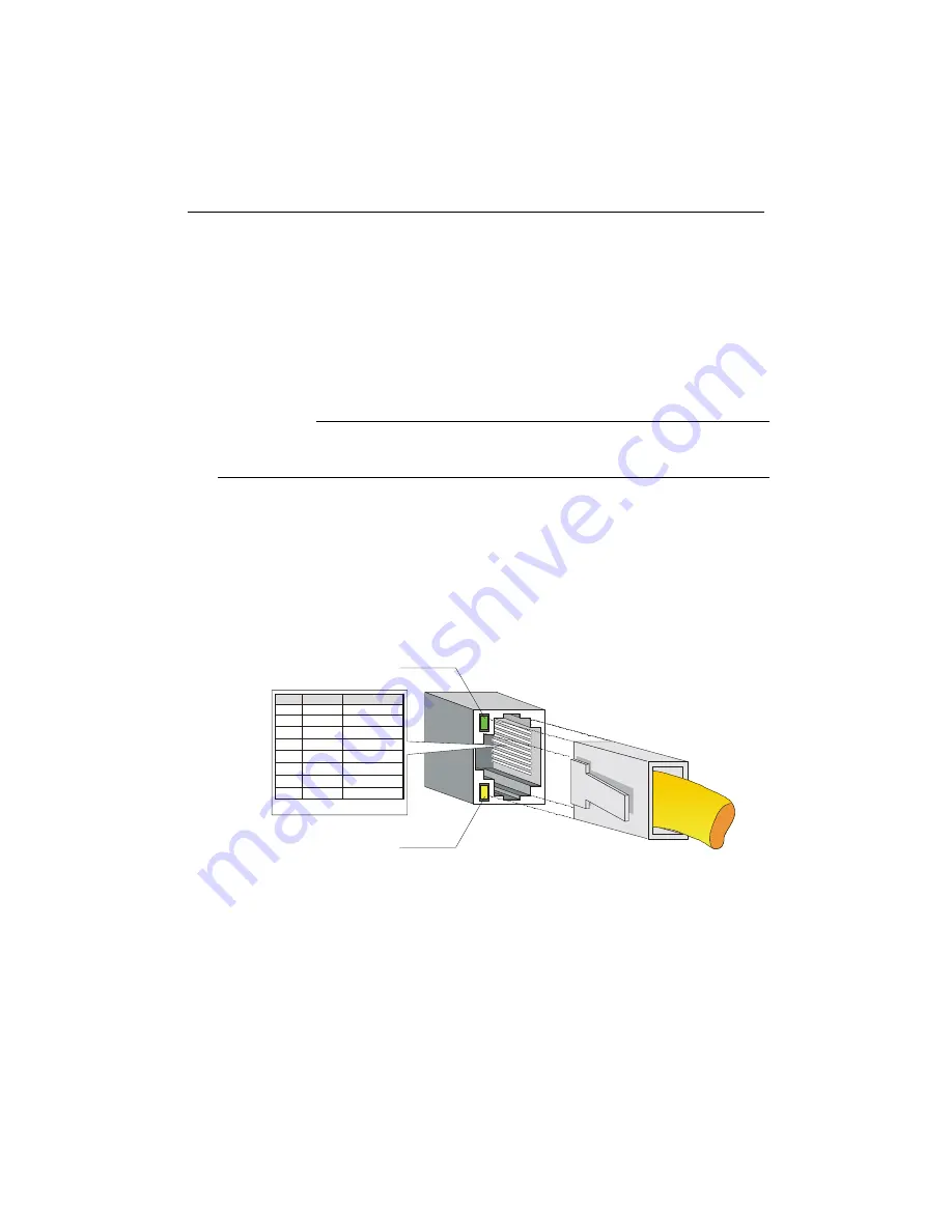
Ethernet 0 and 1 signals are respectively available on J15 and J12 RJ-45
connectors only when the board is ordered for front plate operations.
Activity and link indicators are built in and are described as follows:
1
8
Ethernet 10Base-T and 100Base-TX
1
2
3
4
5
6
7
8
Transmit Data +
Transmit Data -
Receive Data +
Not Connected
Not Connected
Receive Data -
Not Connected
Not Connected
TX+
TX-
RX+
N.C.
N.C.
RX-
N.C.
N.C.
Pin #
I/O
Signal
GREEN:
AMBER:
Link Integrity - If the link is good in either
10 or 100Mbps, the LED lights ON.
Activity - Indicates either transmit or receive
activity (lights ON)
Summary of Contents for TEK-CPCI 1003
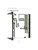
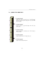
Page 15: ...TEK CPCI 1003 Technical Reference Manual 5 4 5 1 CONNECTOR LOCATION...
Page 22: ...FEATURE DESCRIPTION 7 ONBOARD FEATURES...
Page 51: ...TEK CPCI 1003 Technical Reference Manual 9 2 JUMPER LOCATION...
Page 52: ...Setting Jumpers 9 3 JUMPER SETTINGS Table 1...
Page 53: ...TEK CPCI 1003 Technical Reference Manual 9 4 JUMPER SETTINGS TABLE 2...
Page 67: ...SOFTWARE SETUPS 12 AWARD SETUP PROGRAM 13 UPDATING THE BIOS WITH UPGBIOS 14 VT100 MODE...
Page 95: ...C 1 C BOARD DIAGRAMS C 1 ASSEMBLY TOP DIAGRAM...

