TEK-CPCI-1003 Technical Reference Manual
7-6
7.4 FLOPPY DISK INTERFACE
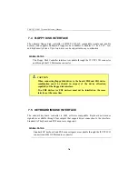
The onboard floppy disk controller is IBM PC XT/AT compatible (single and double
density), and supports Enhanced Floppy mode (2.88MB). It handles 3.5” and 5.25”, low
and high density drives. Up to two drives can be supported in any combination.
SIGNAL PATHS
The Floppy Disk Controller interface is available through the J5 CPCI I/O connector
and through the J19 Mezzanine connector.
CAUTION
When connecting floppy disk drives to the board, FD0 and FD1 device
combination must be shared in respect of the device allocation
capability of the floppy disk interface.
Two FD0 devices (or FD1 devices) must not be installed on the same
interface at the same time.
7.5 KEYBOARD/MOUSE INTERFACE
The onboard keyboard controller is 8042 software compatible. Keyboard and mouse
signals are available through four outputs that support direct connection to the interface.
Standard AT keyboard and PS/2 mouse are supported.
SIGNAL PATHS
Standard AT keyboard and PS/2 mouse signals are available through the J5 CPCI I/O
connector and the J19 Mezzanine connector.
Summary of Contents for TEK-CPCI 1003
Page 15: ...TEK CPCI 1003 Technical Reference Manual 5 4 5 1 CONNECTOR LOCATION...
Page 22: ...FEATURE DESCRIPTION 7 ONBOARD FEATURES...
Page 51: ...TEK CPCI 1003 Technical Reference Manual 9 2 JUMPER LOCATION...
Page 52: ...Setting Jumpers 9 3 JUMPER SETTINGS Table 1...
Page 53: ...TEK CPCI 1003 Technical Reference Manual 9 4 JUMPER SETTINGS TABLE 2...
Page 67: ...SOFTWARE SETUPS 12 AWARD SETUP PROGRAM 13 UPDATING THE BIOS WITH UPGBIOS 14 VT100 MODE...
Page 95: ...C 1 C BOARD DIAGRAMS C 1 ASSEMBLY TOP DIAGRAM...

