TEK-CPCI-1003 Technical Reference Manual
7-10
7.9 SERIAL PORTS
Four full function serial ports are provided on the board for asynchronous serial
communications. They are 16C550 high-speed UART compatible and support 16-byte FIFO
buffers for transfer rates at up to 230 and 460Kbaud.
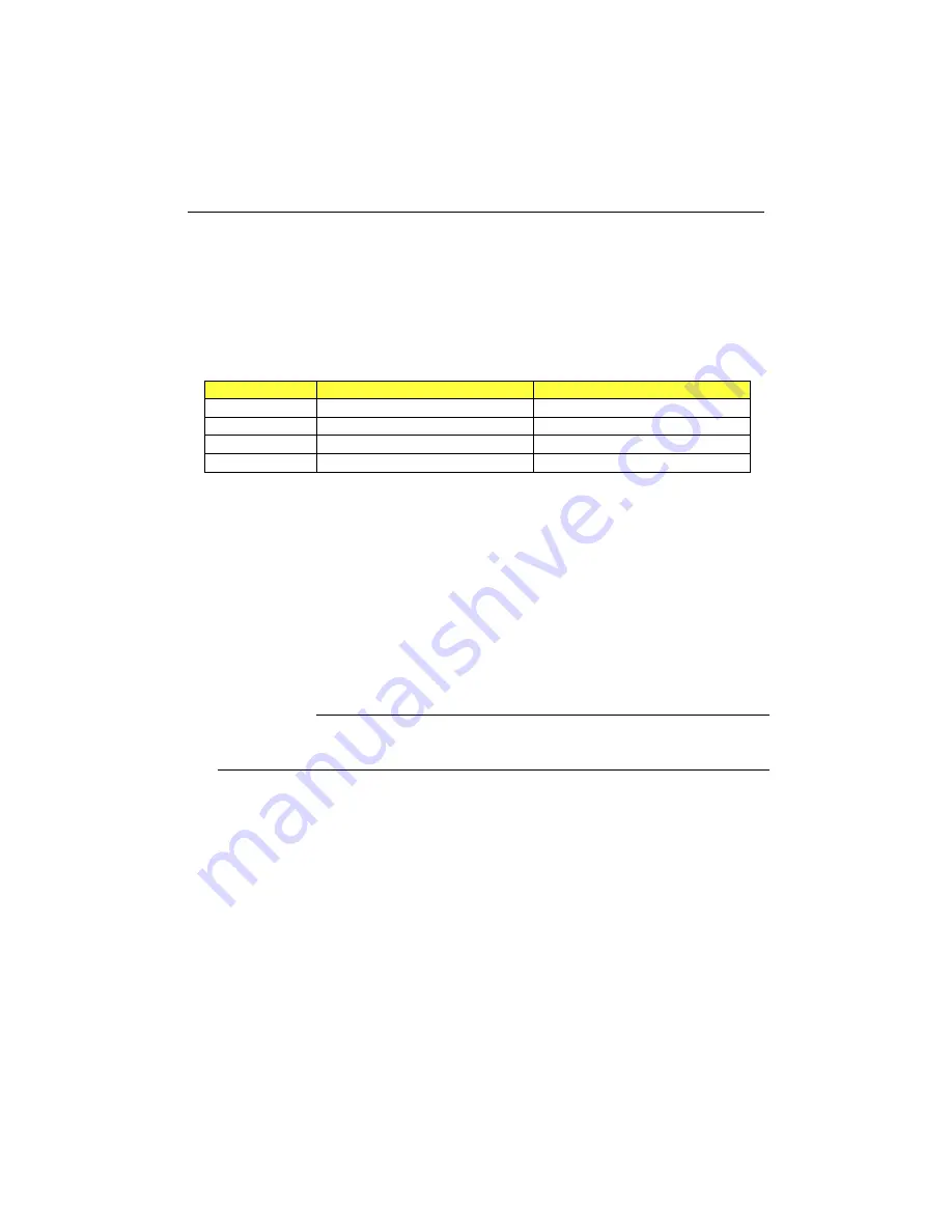
Each serial port is specified as follows:
Designation
Communication Mode
Output Path
Serial Port 1
RS-232
Front Plate DB-9 J10, CPCI J5
Serial Port 2
RS-232
CPCI J3
Serial Port 3
RS-232, RS-422, RS-485, Infrared
CPCI J3, CPCI J5
Serial Port 4
RS-232
CPCI J3
UART registers are individually addressable and fully programmable
7.9.1 Serial Port 1
Serial Port 1 is buffered directly for RS-232 operation. Signals include the complete signal set
for handshaking, modem control, interrupt generation, and data transfer. When assigned as
COM1, the port is 100% compatible with the IBM-AT serial port in RS-232 mode.
SIGNAL PATH
Serial Port 1 signal path depends on the output configuration you have ordered for the
board.
§
Front Plate Configuration
Serial Port1 signals are available through the J10 DB-9 connector located
on the front plate. In this configuration the port is 100% compatible with
the IBM-AT serial port specification.
§
CPCI I/O Configuration
The complete signal set is tied to the J5 CPCI I/O connector to be used
through a backplane
Summary of Contents for TEK-CPCI 1003
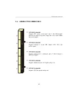
Page 15: ...TEK CPCI 1003 Technical Reference Manual 5 4 5 1 CONNECTOR LOCATION...
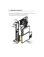
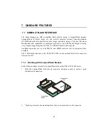
Page 22: ...FEATURE DESCRIPTION 7 ONBOARD FEATURES...
Page 51: ...TEK CPCI 1003 Technical Reference Manual 9 2 JUMPER LOCATION...
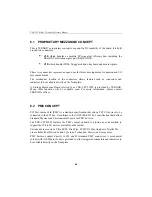
Page 52: ...Setting Jumpers 9 3 JUMPER SETTINGS Table 1...
Page 53: ...TEK CPCI 1003 Technical Reference Manual 9 4 JUMPER SETTINGS TABLE 2...
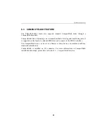
Page 67: ...SOFTWARE SETUPS 12 AWARD SETUP PROGRAM 13 UPDATING THE BIOS WITH UPGBIOS 14 VT100 MODE...
Page 95: ...C 1 C BOARD DIAGRAMS C 1 ASSEMBLY TOP DIAGRAM...

