TEK-CPCI-1003 Technical Reference Manual
7-12
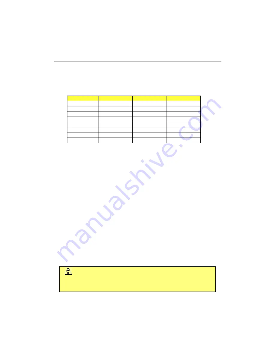
Upon a power-up or reset, the Serial Port 3 interface circuits are automatically configured for
the operation mode setup in the BIOS. The Serial Port 3 signal assignation on the J5 CPCI
I/O connector depends on the operation mode (RS-232, RS-422, or RS-485) it has been set:
Pin Number (J5)
RS-232
RS-422
RS-485
A11
/JDCD2
/DCD
/DCD
C11
JRXD2
RX(-)
RX/TX(-)
D11
/JDSR2
DSR
DSR
E11
JTXD2
TX(-)
-
A12
/JRTS2
RX(+)
RX/TX(+)
B12
/JCTS2
TX(+)
-
C12
/JRI2
/RI
/RI
E12
/JDTR2
/DTR
/DTR
To configure the Serial Port 3 operation mode, use the BIOS setup program. See Section
12.3.7 -
Integrated Peripherals
.
§
Infrared Mode:
Infrared (IR) interface signals are provided to drive IR module for remote operations
through Serial Port 3. When set in IR mode, the IR interface supports multi-protocol
infrared operations. The IR interface is IrDA 1.1 compliant, and supports TEMIC/HP
modules, SHARP ASK IR, and consumer IR.
§
RS-232 Protocol:
When configured for RS-232 operation mode, the Serial Port 3 is 100% compatible with
the IBM-AT serial port signals.
§
RS-422 Protocol:
The RS-422 protocol (Full Duplex) uses both RX and TX lines during a communication
session.
There are no user software restrictions except that software must not attempt to use the
handshake line because they are not connected. However, handshaking by software only
(XON-XOFF) may be used.
CAUTION
In RS-422 mode, W9 and W10 jumper caps must be installed to connect
the 120 ohms termination resistors (See Section 10 –
Jumper Settings
).
Summary of Contents for TEK-CPCI 1003
Page 15: ...TEK CPCI 1003 Technical Reference Manual 5 4 5 1 CONNECTOR LOCATION...
Page 22: ...FEATURE DESCRIPTION 7 ONBOARD FEATURES...
Page 51: ...TEK CPCI 1003 Technical Reference Manual 9 2 JUMPER LOCATION...
Page 52: ...Setting Jumpers 9 3 JUMPER SETTINGS Table 1...
Page 53: ...TEK CPCI 1003 Technical Reference Manual 9 4 JUMPER SETTINGS TABLE 2...
Page 67: ...SOFTWARE SETUPS 12 AWARD SETUP PROGRAM 13 UPDATING THE BIOS WITH UPGBIOS 14 VT100 MODE...
Page 95: ...C 1 C BOARD DIAGRAMS C 1 ASSEMBLY TOP DIAGRAM...

