Onboard Features
7-13
§
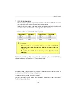
RS-485 Protocol:
The RS-485 protocol (Half Duplex) also uses differential signals during a communication
session. It differs from the RS-422 mode as it offers the ability to transmit and receive over
the same pair of wires, and allows the sharing of the communication line by multiple stations.
This configuration (also known as Party Line) allows only one system to take control of the
communication line at the time.
In RS-485 mode, the RX lines are used as the transceiver lines, and the RTS signal is used
to control the direction of the RS-485 buffer.
When set for RS-485 mode in the BIOS, upon power-up or reset, the transceiver is by
default in receiver mode to prevent unwanted perturbation on the line. Party line operation
mode requires termination resistors to be installed at both ends of the network.
CAUTION
When installing the TEK-CPCI-1003 at one end of the network, W9
and W10 jumper caps must be installed to connect the 120 ohms
termination resistors (See Section 10 –
Jumper Settings
).
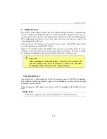
7.9.4 Serial Port 4
The Serial Port 4 is buffered directly for RS-232 operations and is 16C550 PC-Compatible.
The interface includes the complete signal set for handshaking, modem control, interrupt
generation, and data transfer.
When assigned as COM4 logical port, the port is 100% compatible with the IBM-AT serial
port.
SIGNAL PATH
Serial Port 4 signals are only available through the J3 CPCI I/O connector.
Summary of Contents for TEK-CPCI 1003
Page 15: ...TEK CPCI 1003 Technical Reference Manual 5 4 5 1 CONNECTOR LOCATION...
Page 22: ...FEATURE DESCRIPTION 7 ONBOARD FEATURES...
Page 51: ...TEK CPCI 1003 Technical Reference Manual 9 2 JUMPER LOCATION...
Page 52: ...Setting Jumpers 9 3 JUMPER SETTINGS Table 1...
Page 53: ...TEK CPCI 1003 Technical Reference Manual 9 4 JUMPER SETTINGS TABLE 2...
Page 67: ...SOFTWARE SETUPS 12 AWARD SETUP PROGRAM 13 UPDATING THE BIOS WITH UPGBIOS 14 VT100 MODE...
Page 95: ...C 1 C BOARD DIAGRAMS C 1 ASSEMBLY TOP DIAGRAM...

