TEK-CPCI-1003 Technical Reference Manual
7-16
7.12 VIDEO INTERFACE
The high-performance video capability of the board is based on the latest Accelerated
Graphics Port (AGP) technology. The video controller, CL-GD5465 from Cirrus Logic,
connects directly to the Primary PCI bus, and interfaces with 2MB onboard video memory
through the Rambus channel (600MB/sec bandwidth).
64-bit 2D/3D graphics engine, 64-bit GUI accelerator engine with multiple window video
acceleration, and Enhanced V-Port interface are some of the major video features.
SIGNAL PATH
The VGA video signal path depends on the output configuration you have ordered for
the board.
§
Front Plate Configuration
VGA interface signals are available on J8 standard SVGA video connector,
located on the front plate of the board, only when the board is ordered for front
plate operations. This configuration allows direct connection of CRT display
onto the board.
§
CPCI I/O Configuration
VGA interface signals are available on J4 CPCI I/O connector only when the board is
ordered for rear panel output operations.
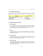
Setting the board to operate in rear panel output configuration requires the installation of
zero ohm resistors to connect signals to the CPCI connector. Resistor references are
listed in the following table:
Video Signals
0 ohm Location:
VSDA1
R116
VSCL1
R115
BLUE
R118
GREEN
R113
RED
R114
VSYNC
R100
HSYNC
R101
Summary of Contents for TEK-CPCI 1003
Page 15: ...TEK CPCI 1003 Technical Reference Manual 5 4 5 1 CONNECTOR LOCATION...
Page 22: ...FEATURE DESCRIPTION 7 ONBOARD FEATURES...
Page 51: ...TEK CPCI 1003 Technical Reference Manual 9 2 JUMPER LOCATION...
Page 52: ...Setting Jumpers 9 3 JUMPER SETTINGS Table 1...
Page 53: ...TEK CPCI 1003 Technical Reference Manual 9 4 JUMPER SETTINGS TABLE 2...
Page 67: ...SOFTWARE SETUPS 12 AWARD SETUP PROGRAM 13 UPDATING THE BIOS WITH UPGBIOS 14 VT100 MODE...
Page 95: ...C 1 C BOARD DIAGRAMS C 1 ASSEMBLY TOP DIAGRAM...

