Onboard Features
7-17
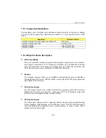
7.12.1 Supported Resolutions
The maximum video resolution and performance depend directly on the drivers running
with your software application. Resolution and number of colors specification are listed
below:
Resolution
Number of Colors
640x480, 800x600, 1024x768, 1280x1024, 1600x1200
256 (8 bits)
640x480, 800x600, 1024x768
65,536 (16 bits)
640x480, 800x600
16.8 million (24 bits)
640x480, 800x600
16.8 million (32 bits)
7.12.2 Major Features Description
§
VGA Compatibility
The video controller includes all registers and data paths required for VGA controllers,
and supports extensions to VGA, including resolutions up to 800x600x16.8 million
colors non-interlaced. 16-bit images are displayed at up to 1024x768 resolution, and
256-color modes can reach a maximum of 1600x1200 resolution.
§
Rambus
The Rambus interface offers up to 600MB/sec bandwidth. Memory bandwidth is
allocated during CPU access, DRAM refresh, screen refresh, 2D/3D engine operations,
and Enhanced V-Port access.
§
2D Graphics Engine
The 2D graphics engine is an advanced 64-bit three-operand engine that accelerates
BitBLTs as line draws, polygon draw, and polygon fill. The 2D graphics engine also
performs video and bitmap scaling, and data overlay.
§
3D Graphics Engine
The 3D graphics engine can draw randomly oriented triangles with Gouraud shading,
texture mapping, alpha blending, and Z-buffering. It uses AGP/PCI bus mastering to
fetch instructions and parameters from system memory to render scenes with a
minimum of host intervention.
Summary of Contents for TEK-CPCI 1003
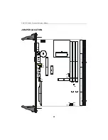
Page 15: ...TEK CPCI 1003 Technical Reference Manual 5 4 5 1 CONNECTOR LOCATION...
Page 22: ...FEATURE DESCRIPTION 7 ONBOARD FEATURES...
Page 51: ...TEK CPCI 1003 Technical Reference Manual 9 2 JUMPER LOCATION...
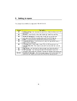
Page 52: ...Setting Jumpers 9 3 JUMPER SETTINGS Table 1...
Page 53: ...TEK CPCI 1003 Technical Reference Manual 9 4 JUMPER SETTINGS TABLE 2...
Page 67: ...SOFTWARE SETUPS 12 AWARD SETUP PROGRAM 13 UPDATING THE BIOS WITH UPGBIOS 14 VT100 MODE...
Page 95: ...C 1 C BOARD DIAGRAMS C 1 ASSEMBLY TOP DIAGRAM...

