TEK-CPCI-1003 Technical Reference Manual
8-4
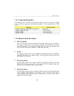
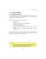
The recommended DIMM devices are listed in the table below. Many other models are
available and function equally well. Users are encouraged to check with their local
distributors for comparable substitutes.
SDRAM DIMM Module
VENDOR
PART NUMBER
MRP Code
32MB - 4M*72
ROCKY MOUNTAIN RAM
4x72CQ2x8S4E
635-049
CENTON
CFEKG1TTNVU367G
128MB - 16M*72
ROCKY MOUNTAIN RAM
16x72CQ8x8S4E
635-050
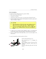
8.3.2 DIMM Installation
To install the DIMMs in the sockets, proceed as follows:
1.
With the board flat on the table, turn it so that the front plate is facing you.
2.
Hold the module vertically so that the bottom connector key is on the right. Insert
the fingers into the socket. The socket’s keys will ensure a correct mating.
3.
Press firmly on the top edge of the memory module to engage it into the socket. The
module is fully inserted when the retaining clips snap into notches located at each
end of the module.
If necessary, work your way by inserting the other modules, one by one.
To remove the DIMMs from the sockets, pull simultaneously on the retaining clips located on
each side of the socket. Once the module has snapped out, pull gently on it.
Summary of Contents for TEK-CPCI 1003
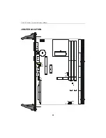
Page 15: ...TEK CPCI 1003 Technical Reference Manual 5 4 5 1 CONNECTOR LOCATION...
Page 22: ...FEATURE DESCRIPTION 7 ONBOARD FEATURES...
Page 51: ...TEK CPCI 1003 Technical Reference Manual 9 2 JUMPER LOCATION...
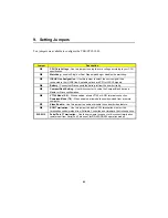
Page 52: ...Setting Jumpers 9 3 JUMPER SETTINGS Table 1...
Page 53: ...TEK CPCI 1003 Technical Reference Manual 9 4 JUMPER SETTINGS TABLE 2...
Page 67: ...SOFTWARE SETUPS 12 AWARD SETUP PROGRAM 13 UPDATING THE BIOS WITH UPGBIOS 14 VT100 MODE...
Page 95: ...C 1 C BOARD DIAGRAMS C 1 ASSEMBLY TOP DIAGRAM...


