Building a CPCI System
10-3
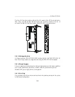
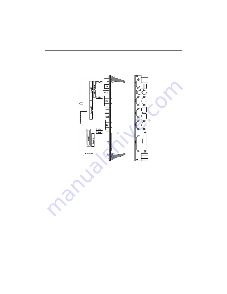
The Rear I/O Transition module gathers all the I/O signals of the CPU board and makes
them easily accessible through standard headers and connectors located at the rear of
enclosure. The Rear I/O Transition module (TEK-CPCI-1071) is illustrated below:
10.1.3 Storage Devices
A storage mezzanine (TEK-CPCI-1050/1051) attaches directly to the TEK-CPCI-1003. 6U
form factor storage modules are supported when using the TEK-CPCI-1103 backplane.
10.1.4 Power Supply
6U power supply modules featuring load sharing redundant mode and hot-swap capabilities
allow on-site replacements of defective a module while the system remains powered.
Standard ATX power supply units are also supported.
10.1.5 Fan Tray
The ventilation unit of the enclosure must conform to the global requirement of the system
in fully loaded configuration.
Summary of Contents for TEK-CPCI 1003
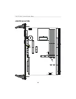
Page 15: ...TEK CPCI 1003 Technical Reference Manual 5 4 5 1 CONNECTOR LOCATION...
Page 22: ...FEATURE DESCRIPTION 7 ONBOARD FEATURES...
Page 51: ...TEK CPCI 1003 Technical Reference Manual 9 2 JUMPER LOCATION...
Page 52: ...Setting Jumpers 9 3 JUMPER SETTINGS Table 1...
Page 53: ...TEK CPCI 1003 Technical Reference Manual 9 4 JUMPER SETTINGS TABLE 2...
Page 67: ...SOFTWARE SETUPS 12 AWARD SETUP PROGRAM 13 UPDATING THE BIOS WITH UPGBIOS 14 VT100 MODE...
Page 95: ...C 1 C BOARD DIAGRAMS C 1 ASSEMBLY TOP DIAGRAM...


