TEK-CPCI-1003 Technical Reference Manual
10-4
10.2 INSTALLING THE BOARD INTO A BAY
The TEK-CPCI-1003 is a mechanical Eurocard form factor board. It takes advantages of the
IEEE1101.10 specifications that ensure a mechanical interchange capability between
different plug-in elements in sub-racks.
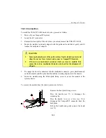
Due to the high-density pinout of the Hard Metric connector, some precautions must be taken
when connecting or disconnecting a board to/from a backplane:
1.
Rail guides must be installed on the enclosure to slide the board to the backplane.
2.
Do not use force if there is any mechanical resistance while inserting the board.
3.
Screw the front plate to the enclosure to firmly attach the board to its enclosure.
4.
Use the extractor handles to disconnect and extract the board from its enclosure.
10.2.1 Connector Keying
CompactPCI connector support guide lugs to ensure a correct polarized mating. A proper
mating is enhanced by the use of coding keys for 3.3V and 5V operation.
Coding keys prevent inadvertent installation of a 5V peripheral board in a 3.3V slot. The
TEK-CPCI-1003 is universal. It does not support coding key. The PCI bus does not require
to be keyed. Backplane connectors must always be keyed according to the signaling (VIO)
level.
Coding Key Colors are defined as follows:
Signaling Voltage
Key Color
3.3V
Cadmium Yellow
5V
Brilliant Blue
Universal board (5V and 3.3V)
none
10.2.2 Bus Mastering
The TEK-CPCI-1003 provides seven pairs of REQ/GNT (0-7) arbitration signals through
the Secondary PCI bus. This means the board is capable of driving up to seven CPCI slots
with PCI Bus Master capabilities.
Summary of Contents for TEK-CPCI 1003
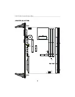
Page 15: ...TEK CPCI 1003 Technical Reference Manual 5 4 5 1 CONNECTOR LOCATION...
Page 22: ...FEATURE DESCRIPTION 7 ONBOARD FEATURES...
Page 51: ...TEK CPCI 1003 Technical Reference Manual 9 2 JUMPER LOCATION...
Page 52: ...Setting Jumpers 9 3 JUMPER SETTINGS Table 1...
Page 53: ...TEK CPCI 1003 Technical Reference Manual 9 4 JUMPER SETTINGS TABLE 2...
Page 67: ...SOFTWARE SETUPS 12 AWARD SETUP PROGRAM 13 UPDATING THE BIOS WITH UPGBIOS 14 VT100 MODE...
Page 95: ...C 1 C BOARD DIAGRAMS C 1 ASSEMBLY TOP DIAGRAM...

