Building a CPCI System
10-5
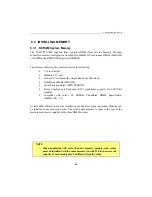
10.2.3 Connection
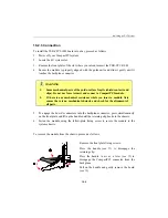
To install the TEK-CPCI-1003 board into a bay, proceed as follows:
1.
Power off your CompactPCI system
2.
Locate the 6U system slot
3.
Remove the front plate of the slot where you intend to insert the TEK-CPCI-1003
4.
Ensure the module is properly aligned with the guide-rails and slide it gently until it
touches the backplane connector
WARNING
1.
Some mechanical parts of the guide-rail are fragile (shield contacts and
clips). Do not use force to insert and connect a CompactPCI module.
2.
If there is any mechanical resistance while you insert a module, first
ensure there is no mechanical obstacle and check for the alignment of
all parts.
5.
To engage the board’s connectors into the backplane connector, press simultaneously
on the front plate and lift up the handle until the retaining clip hooks to the chassis.
6.
Fasten the module using the fellow-plate fixing screw to secure the module to the
system chassis.
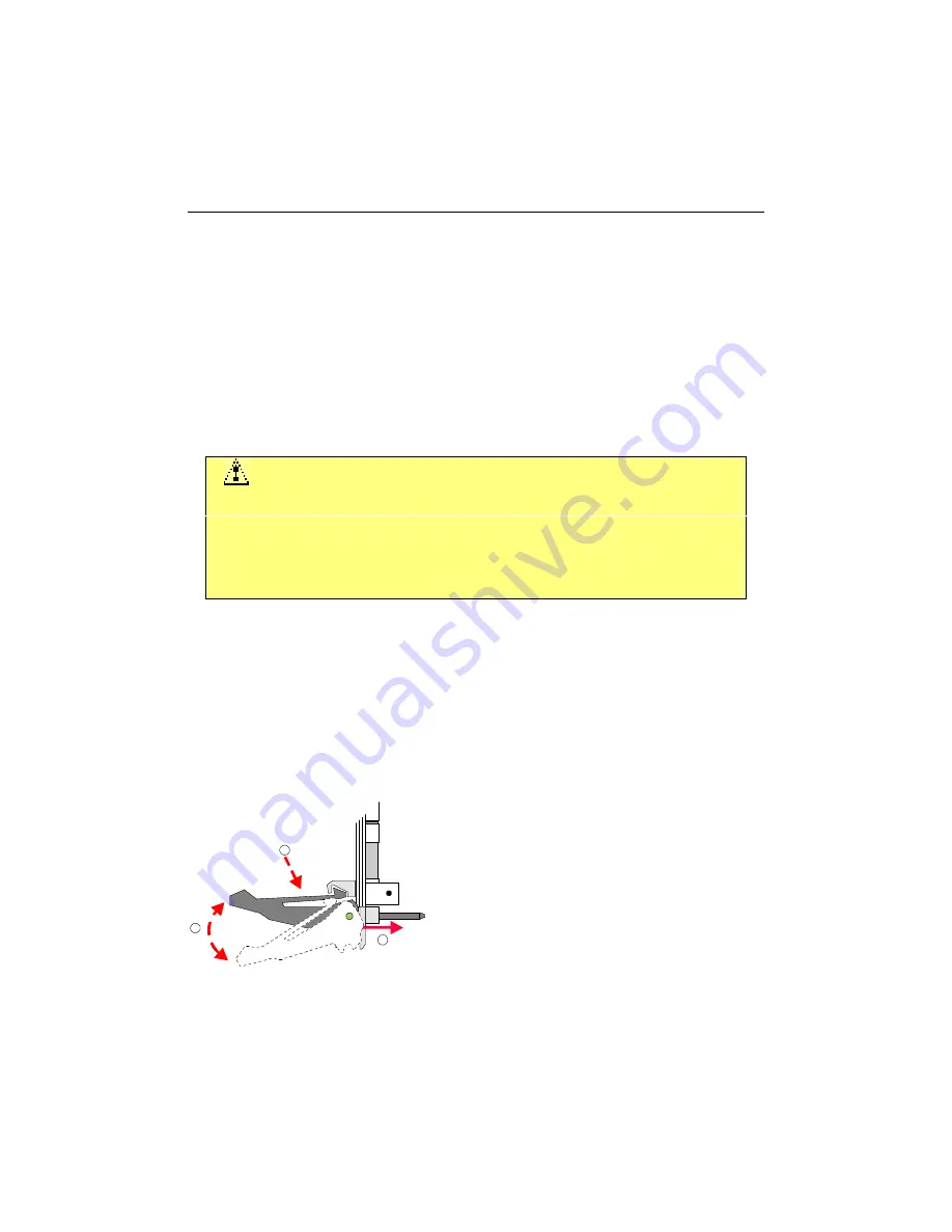
To remove the module from the chassis, proceed as follows:
1
2
3
Remove the front plate fixing screws.
Press the handle (see
¬
) to disengage the
retaining clip.
Press the handle to act as a lever (see
-
) to
disengage the CompactPCI connector from the
backplane.
Pull on the handle and gently remove the board
(see
®
).
Summary of Contents for TEK-CPCI 1003
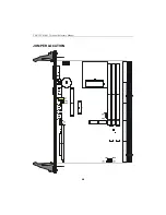
Page 15: ...TEK CPCI 1003 Technical Reference Manual 5 4 5 1 CONNECTOR LOCATION...
Page 22: ...FEATURE DESCRIPTION 7 ONBOARD FEATURES...
Page 51: ...TEK CPCI 1003 Technical Reference Manual 9 2 JUMPER LOCATION...
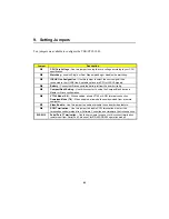
Page 52: ...Setting Jumpers 9 3 JUMPER SETTINGS Table 1...
Page 53: ...TEK CPCI 1003 Technical Reference Manual 9 4 JUMPER SETTINGS TABLE 2...
Page 67: ...SOFTWARE SETUPS 12 AWARD SETUP PROGRAM 13 UPDATING THE BIOS WITH UPGBIOS 14 VT100 MODE...
Page 95: ...C 1 C BOARD DIAGRAMS C 1 ASSEMBLY TOP DIAGRAM...

