AWARD Setup Program
12-3
12.2 USING AWARD SETUP PROGRAM
The arrow keys (
↑
↓
→
←
) are used to highlight items on the menu and the PAGEUP and
PAGEDOWN keys are used to change the entry values for the highlighted item. To select an
entry, press the ENTER key. Also, you can press the F1 key to obtain help information or the
ESC key to leave an option, close a menu or to quit the program.
12.2.1 Using AWARD Setup Program
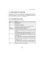
To navigate in the Setup program, proceed as follows:
Key
Function
↑
Moves to previous item.
↓
Moves to next item.
←
Moves to the item in the left hand.
→
Moves to the item in the right hand.
ESC
In the Main Menu: Quits program (Answer ‘Y’ to save changes into CMOS).
When in other screens: Exits and returns to the Main Menu.
PAGEUP or +
Increases the numeric value or changes value.
PAGEDOWN or -
Decreases the numeric value or changes value.
F5
In the Main Menu: Restores the previous setup values for all the BIOS
parameters (except Standard CMOS) which were displayed when you entered
the program.
In BIOS Features Setup, Chipset Features Setup, Power Management Setup,
Thermal Management Setup, PNP/PCI Setup or Integrated Peripherals Setup:
Restores the previous setup values for that setup screen only.
F6
In the Main Menu: Loads the BIOS Defaults of all the BIOS parameters (except
Standard CMOS). The BIOS Defaults are fail safe settings that consist of the
safest set of parameters.
In BIOS Features Setup, Chipset Features Setup, Power Management Setup,
Thermal Management Setup, PNP/PCI Setup or Integrated Peripherals Setup:
Loads the BIOS Defaults for all the BIOS parameters for that setup screen
only.
F7
In the Main Menu: Loads the Setup Defaults for all the BIOS parameters
(except Standard CMOS).
In BIOS Features Setup, Chipset Features Setup, Power Management Setup,
Thermal Management Setup, PNP/PCI Setup or Integrated Peripherals Setup:
Loads the Setup Defaults for all the BIOS parameters for that setup screen
only.
F10
In the Main Menu: Saves all the CMOS changes.
Summary of Contents for TEK-CPCI 1003
Page 15: ...TEK CPCI 1003 Technical Reference Manual 5 4 5 1 CONNECTOR LOCATION...
Page 22: ...FEATURE DESCRIPTION 7 ONBOARD FEATURES...
Page 51: ...TEK CPCI 1003 Technical Reference Manual 9 2 JUMPER LOCATION...
Page 52: ...Setting Jumpers 9 3 JUMPER SETTINGS Table 1...
Page 53: ...TEK CPCI 1003 Technical Reference Manual 9 4 JUMPER SETTINGS TABLE 2...
Page 67: ...SOFTWARE SETUPS 12 AWARD SETUP PROGRAM 13 UPDATING THE BIOS WITH UPGBIOS 14 VT100 MODE...
Page 95: ...C 1 C BOARD DIAGRAMS C 1 ASSEMBLY TOP DIAGRAM...

