TEK-CPCI-1003 Technical Reference Manual
12-6
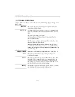
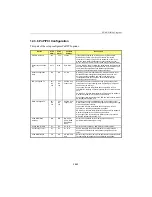
12.3.1 Standard CMOS Setup
This part of the setup allows you to set the time, date, hard disk type, types of floppy drives
and video type.
Date/Time
The current values for each category are displayed. Enter new
values through the keyboard.
Hard Disks
Two IDE controllers are defined on the board. The Primary and
Secondary controller can have two disks: Master Disk or Slave
Disk.
The disks are bootable in this order:
1) Primary Master, 2) Primary Slave, 3) Secondary Master,
and 4) Secondary Slave.
The W5 jumper configures the CompactFlash disk as Secondary
Master or Secondary Slave device.
Only three settings are available for the hard disk type: Auto, 47
(user defined) and None. Type 1 to 46 are not predefined in the
system: Use auto-detect or enter the parameters for the type in the
user-defined type 47.
Drive A / Drive B
Select the type of floppy disk installed for drive A and drive B.
Video
This option specifies the basic type of display adapter card
installed in the system.
Halt on
This option specifies the type of errors that will stop the system
during the BIOS booting procedure. A message asks that you
press F1 to continue or press the DELETE key to enter Setup.
The settings are: All errors, No errors, All but keyboard, All but
diskette, and All but disk/key (default setting).
Memory
This display-only option indicates the amount of Base, Extended
and other types of memory installed in the system.
Summary of Contents for TEK-CPCI 1003
Page 15: ...TEK CPCI 1003 Technical Reference Manual 5 4 5 1 CONNECTOR LOCATION...
Page 22: ...FEATURE DESCRIPTION 7 ONBOARD FEATURES...
Page 51: ...TEK CPCI 1003 Technical Reference Manual 9 2 JUMPER LOCATION...
Page 52: ...Setting Jumpers 9 3 JUMPER SETTINGS Table 1...
Page 53: ...TEK CPCI 1003 Technical Reference Manual 9 4 JUMPER SETTINGS TABLE 2...
Page 67: ...SOFTWARE SETUPS 12 AWARD SETUP PROGRAM 13 UPDATING THE BIOS WITH UPGBIOS 14 VT100 MODE...
Page 95: ...C 1 C BOARD DIAGRAMS C 1 ASSEMBLY TOP DIAGRAM...

