AWARD Setup Program
12-11
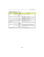
Power Management Setup
(Continued)
Option
BIOS
Default
Setup
Default
Possible
Settings
Description
Throttle Duty Cycle
75.0%
75.0%
12.5%, 25.0%,
37.5%, 50.0%,
62.5%,
75.0%
When the system enters Doze mode, the CPU clock runs only
part of the time. You may select the percentage of time that the
clock does not run.
VGA Active Monitor
En.
En.
En., Dis.
When Enabled, any video activity restarts the global timer for
Standby mode.
Resume by Ring
Dis.
En.
En., Dis.
When Enabled and a modem is connected to a COM port, allows
a modem ring to re-activate the CPU when in Suspend mode.
Resume by Alarm
Dis.
Dis.
En., Dis.
When Enabled, allows setup of a time to re-activate the CPU
when in Suspend mode with the options Date (of Month) Alarm
and Time (hh:mm:ss) Alarm.
Note: The IRQ 8 Break Suspend option in this setup screen
must be Enabled to use the RTC alarm.
Date (of Month) Alarm
-
-
From 0 to 31
This option appears only if Resume by Alarm is enabled. It
specifies the date in the month for the RTC alarm.
Time (hh:mm:ss)
Alarm
-
-
from 0:0:0 to
23:59:59
This option appears only if Resume by Alarm is enabled. It
specifies time of day for the RTC alarm.
IRQ 8 Break Suspend
Dis.
En.
En., Dis.
When Enabled, the RTC alarm interrupt is monitored to allow an
interrupt to awaken the system when in Doze, Standby or
Suspend Mode.
Reload Global Timer
Events:
When any of the options below is Enabled, monitoring of the
interrupt will occur to allow an interrupt to awaken the system
when in Doze, Standby or Suspend Mode.
IRQ[3-7,9-15], NMI
Dis.
En.
En., Dis.
Primary IDE 0
Dis.
Dis.
En., Dis.
Primary IDE 1
Dis.
Dis.
En., Dis.
Secondary IDE 0
Dis.
Dis.
En., Dis.
Secondary IDE 1
Dis.
Dis.
En., Dis.
Floppy Disk
Dis.
Dis.
En., Dis.
Serial Port
En.
En.
En., Dis.
Parallel Port
Dis.
Dis.
En., Dis.
Summary of Contents for TEK-CPCI 1003
Page 15: ...TEK CPCI 1003 Technical Reference Manual 5 4 5 1 CONNECTOR LOCATION...
Page 22: ...FEATURE DESCRIPTION 7 ONBOARD FEATURES...
Page 51: ...TEK CPCI 1003 Technical Reference Manual 9 2 JUMPER LOCATION...
Page 52: ...Setting Jumpers 9 3 JUMPER SETTINGS Table 1...
Page 53: ...TEK CPCI 1003 Technical Reference Manual 9 4 JUMPER SETTINGS TABLE 2...
Page 67: ...SOFTWARE SETUPS 12 AWARD SETUP PROGRAM 13 UPDATING THE BIOS WITH UPGBIOS 14 VT100 MODE...
Page 95: ...C 1 C BOARD DIAGRAMS C 1 ASSEMBLY TOP DIAGRAM...

