Memory & I/O Maps
B-3
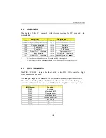
B.3 IRQ LINES
The board is fully PC compatible with interrupt steering for PCI plug and play
compatibility.
Controller # 1
Controller # 2
IRQ 0
Timer Output 0
IRQ 8
Real-Time Clock
IRQ 1
Keyboard (Output Buffer Full)
IRQ 9
Available
1
IRQ 2
Cascade Controller # 2
IRQ 10
Available
1
IRQ 3
Serial Port 2 *
IRQ 11
Available
1
IRQ 4
Serial Port 1 *
IRQ 12
PS/2 Mouse
IRQ 5
Parallel Port 2 * or Available
1
IRQ 13
Coprocessor Error
IRQ 6
Floppy Controller *
IRQ 14
Primary IDE * or available
1
IRQ 7
Parallel Port 1 * or Available
1
IRQ 15
Secondary IDE * or available
1
*
All functions marked with an asterisk (*) can be disabled or reconfigured.
1
Available lines service on board and external PCI/ISA PnP devices or a Legacy ISA device.
B.4 DMA CHANNELS
The TEK-CPCI-1003 integrates the functionality of two 8237 DMA controllers. Eight
DMA channels are available.
According to Plug and Play standards, the system BIOS automatically allocates DMA
Channel 1 or 3 for the parallel port's ECP mode. Channel 2 is reserved for the floppy
controller and Channel 4 is used to cascade Channels 0 through 7 to the microprocessor.
DMA Channel
Function
DMA 0
Available
DMA 1
PnP available (ECP)
DMA 2
Floppy controller
DMA 3
PnP available (ECP)
DMA 4
Cascade controller # 1
DMA 5
PnP available
DMA 6
PnP available
DMA 7
PnP available
Summary of Contents for TEK-CPCI 1003
Page 15: ...TEK CPCI 1003 Technical Reference Manual 5 4 5 1 CONNECTOR LOCATION...
Page 22: ...FEATURE DESCRIPTION 7 ONBOARD FEATURES...
Page 51: ...TEK CPCI 1003 Technical Reference Manual 9 2 JUMPER LOCATION...
Page 52: ...Setting Jumpers 9 3 JUMPER SETTINGS Table 1...
Page 53: ...TEK CPCI 1003 Technical Reference Manual 9 4 JUMPER SETTINGS TABLE 2...
Page 67: ...SOFTWARE SETUPS 12 AWARD SETUP PROGRAM 13 UPDATING THE BIOS WITH UPGBIOS 14 VT100 MODE...
Page 95: ...C 1 C BOARD DIAGRAMS C 1 ASSEMBLY TOP DIAGRAM...

