Connector Pinouts D-8
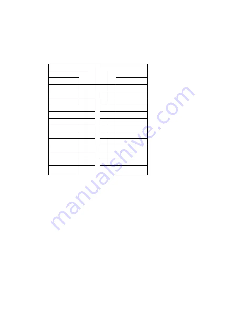
Printer Parallel Port (J13) - Standard Mode - Pinout
Pin Number
Pin Number
Signal Flow
Signal Flow
Signal
Signal
STROBE*
O
1
2
O
AUTOFD*
D0
I/O
3
4
I
ERROR*
D1
I/O
5
6
O
INIT*
D2
I/O
7
8
O
SELECTIN*
D3
I/O
9
10
-
GND
D4
I/O
11
12
-
GND
D5
I/O
13
14
-
GND
D6
I/O
15
16
-
GND
D7
I/O
17
18
-
GND
ACK*
I
19
20
-
GND
BUSY
I
21
22
-
GND
PE
I
23
24
-
GND
SELECT
I
25
26
-
GND
*
Active low signal
Summary of Contents for VIPer808
Page 21: ...Installing Memory 2 3 DIAGRAM 2 1 Assembly Top...
Page 22: ...Installing Memory 2 5 DIAGRAM 2 2 Assembly Bottom...
Page 26: ...Setting Jumpers 3 3 DIAGRAM 3 1 VIPer808 Jumper Locations with Default Settings...
Page 28: ...Setting Jumpers 3 6 TABLE 3 1a Jumper Settings W1 W4 W13 W14...
Page 29: ...Setting Jumpers 3 7 TABLE 3 1b AMD DX2 DX4 CPU Jumper Settings W1 W15 W15C...
Page 30: ...Setting Jumpers 3 8 TABLE 3 1c AMD 5x86 CPU Jumper Settings W1 W15 W15C...
Page 31: ...Setting Jumpers 3 9 TABLE 3 1d Intel CPU Jumper Settings W1 W15 W15C...
Page 32: ...Setting Jumpers 3 10 TABLE 3 1e SGS CPU Jumper Settings W1 W15 W15C...
Page 33: ...Setting Jumpers 3 11 TABLE 3 1f Jumper Settings W18 W20 W23...
Page 92: ...Memory I O Maps B 1 APPENDIX B MEMORY I O MAPS B 01 MEMORY MAPS DIAGRAM B 1 Memory Map Diagram...
Page 96: ...Mechanical Layout Block Diagram C 3 DIAGRAM C 1 Mechanical Specifications...


